
User guide


Page 6 Rev. 0040105005 0212
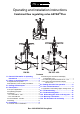
Operating and installation instructions
ASTRA
®
Plus
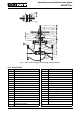
4.4 Technical data - remarks
for
- Principal dimensions
- Pressure-temperature-ratings, etc. see datasheet.
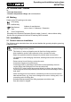
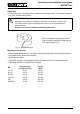
4.5 Marking
Details of the CE-marking on the valve:
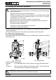
5.0 Installation
5.1 General notes on installation
The following points should be taken into account besides the general principles governing
installation work:
CE-marking
0525 Notified body
Manufacturer
Address of manufacturer:
refer to item 11.0 Warranty / Guarantee
Typ Type
Bj. Year of manufacture
According to the Pressure Equipment Directive table 6, annex II, valves without safety
function are only allowed to bear the CE-marking DN32 onwards.
ATTENTION !
- Remove flange covers if present.
- The interior of valve and pipeline must be free from foreign particles.
- Note installation position with reference to flow, see mark on valve.
- Steam line systems should be designed to prevent water accumulation.
- Lay pipelines so that damaging transverse, bending and torsional forces are
avoided.
- Protect valves from dirt during construction work.
- Connection flanges must mate exactly.
- Connecting bolts for pipe flanges should be mounted preferably from the
counter flange side (hexagon nuts from the valve side).
At DN15-32: If valves should be mounted directly to valves, the upper flange
connecting bolts should be preferably executed with studs and hexagon nuts on
both sides.
- Valve mountings such as actuators, handwheels, hoods must not be used to
take external forces, e.g. they are not designed for use as climbing aids, or as
connecting points for lifting gear.
- Suitable materials handling and lifting equipment should be used.
See data sheet for weights.