
Manual
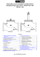
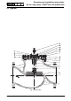
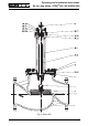
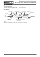
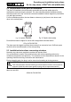
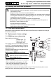
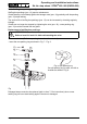
Table Of Contents
- Contents
- 1.0 General information on operating instructions
- 2.0 Notes on possible dangers
- 3.0 Storage and transport
- 4.0 Description
- 5.0 Installation
- 6.0 Putting the valve into operation
- 7.0 Care and maintenance
- 8.0 Troubleshooting
- 9.0 Troubleshooting table
- 10.0 Dismantling the valve or the top part
- 11.0 Warranty / Guarantee
- 12.0 EC declaration of conformity

Page 8 Rev. 0040304002 0410
Operating and installation instructions
Str. thr. stop valves - STEVI
®
405 / 460 (DN300-500)
5.2 Requirements at the place of installation
The place of installation should be easily accessible and provide ample space for
maintenance and removing the actuator. The valve should preferably installed vertically
with the actuator at the top. Inclined or horizontal installation without supports is permissible
only with light actuators.
For this installation position, the two distance columns (or joke) have to be above each
other in the vertical plane.
Permissible actuator weights for valves with unsupported horizontal stems:
65 kg for DN 300-500
The pipes must be lagged to protect the actuators from excessive heat. Sufficient space
must be left for the maintenance of the stem packing.
5.3 Installation Instructions concerning actuators
Normally, stop valves are supplied complete with actuator fitted.
It is not permitted to mantle / dismantle actuators with valves operating and service
conditions (temperature and pressure). The actuators must be assemble as describe in the
operating instructions during conversion and maintenance.
During assembly work, the plug is not be turned on its seating at closing pressure.
When retrofitting actuators, the maximum permissible force for valve actuation must be
taken into account:
Fig. 4: Pipeline vertically Fig. 5: Pipeline horizontally
ATTENTION !
Care must be taken with the bellow type valves when actuators are mounted or
removed. (Hold the valve-stem against turning with an open-end wrench!)
200kN for DN 300-500