A SAFETY MESSAGE A The product for which you have requested information or replacement parishioner BitTorrent product. The replacement models incorporate product designs, safely features, safety Instructions or warnings which represent the latest “State Of The Art” developments. For your safety and those around you please contact your nearest Apprehensively Dealer for a demonstration of the current product safety provisions and features.
Enshrines e Thank You Aries outdoor power equipment is engineered to be the best from start to finish. We have one fundamental belief: Value is not measured solely by price; value is a durable, easy-few-use machine that performs season after season. This manual and the engine manual are your guides. By following the instructions and procedures in them, your Aries equipment will serve you well for many years. The care you give this equipment will determine your overall satisfaction and its service life.
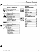
Tale OF CONTENTS Sect Ion Page Section Page Sect Ion 5: Sect Ion 1: INTRODUCTION Genera L MAINTENANCE The Manual 1 Gy Filling Fuel Tank Service and Replacement Parts . 1 Service Position Product Registration ., 1 Engine Cooling Disclaimer 1 Clutch and Brake .. Drive Belt Discharge Chute Deflector Section 2: Surety Transport >| £ Storage .. Safety Alert Symbol 2 Accessories Signal Words.. .2 Maintenance Practices and Laws .2 Required Operator Training . .
S No-THRo Model S Model 838006 (S5322) 3 HP 22" Single Stage Serial Number 000101 and up Model 938007 (§8522) & HP 22" Single Stage Serial Number 000101 and up Model 938008 (S8322E) 3 HP 22" Single Stage, Electric Start Serial Number 000101 and up Modal 938009 (S8522E) 5 HP 22" Single Stage, Electric Start Serial Number 000101 and up Model 938301 (85322) Export 3HP 22" Single Stage Serial Number 000250 and up Model 838303 (88522) Export 5 HP 22" single Stage Serial Number 000101 and up © Copyright 1586 Alan
P 4 SECTION 1: INTRODUCTION Content S + The Manual + Service and Replacement Parts [ + Product Registration I Transform | + Disclaimer model & serial | abet from | | product | registration Introduction L b e THe Manual Before you operate your unit, carefully and completely read manuals supplied with unit. The contents will provide you with an understanding of safety instructions and controls during normal operation and maintenance of your unit. Graphics are provided to help you understand the text.
4 SECTION 2: SAFETY CONTENTS q + Safety Alert Symbol + Safety Decals and Locations » Signal Words + Personal Safety » Practices and Laws + Operational Safety « Required Operator Training + Maintenance and Service Safety Savagery Ale Rt Symbol Notations NOTE : General reference information for proper operation and maintenance practices. This is a safety alert symbol.
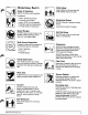
Surety Decals AND Location S ALWAYS replace missing or damaged Safety Decals. Refer to Figure 2 for Safety Decal locations. SAFETY INSTRUCTIONS o0y Keep clear of P PRy 1. SAFETY INSTRUCTIONS 4. Safety Decal (938301,303) 2. SAFETY INSTRUCTIONS (938301,303) A, Attention! Your safety is invoiced! A. Attention! Your safety is involved! g Read " B. Read Owner/Operator Manual. D. fiep ;" s away from total Keep people away from unit during Sl ut off engine and remove key before operation. maintenance. D.
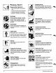
3 sold) Persona L SAFETY Responsible Operators + Only trained audits may operate unit + Training includes actual operation « Clearly understand instructions « Be alert! Conditions can change No Drugs NEVER operate unit after or during consumption of medication, drugs or alcohol. Sate operation requires complete and unimpaired attention at all times., No Alcohol NEVER allow anyone to operate unit when their alertness or coordination is impaired. Safety Gear Wear safety gear to protect body.
P Exr Eon TR Lo solar £ B/ ‘Ovoids B30 It OPERATIONAL SAFETY Rules of Operation KNOW Unit before starting engine, Understand: + How to operate all controls *+ Functions of all controls + How to TOP in an Emergency + Braking & steering characteristics * Turning radius and clearances Speed Ranges DO NOT clear snow at too fast a rate. DO NOT change engine governor setting or over speed engine.
T Clearing Debris & Blockages ALWAYS disengage Impeller, stop engine, remove key and wait for all moving parts to stop before you: leave operators position, unclog unit, make repairs or adjustments or inspections. Check for and repair any damage before restart. Run unit a few minutes after throwing snow to prevent freeze-up of Impeller. Electric Starter Use only approved extension cords and receptacles when starting units equipped with Electric Stater.
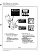
SECTION 3: ASSEMBLY Contents + Dealer Preparation * Delivery Assembly Deal Er PREPARATION Customer Note Your Aries Dealer is expected to complete these preparation steps and review important information, including this manual, with you before or upon delivery of unit or attachment. The preparation information is included here so that you and your dealer may review it together. Handlebar Unit is in handlebar “fold” position for shipping {Figure 3).
. Lower Handle Bar . Upper Handle Bar J-Bolt Knob . J-Bolt Holes . impeller Clutch Bail OO DW= Figure 4 Discharge Chute 8. Remove Rear Cap Screw and Nut from rear of Discharge Chute {Figure 5). 7. Tip Discharge Chute up and install hardware just removed. 8. Tighten hardware at rear of Discharge Chute first, then at sides. . Discharge Chute .Eat Cap Screw and Nut 3 . Side Hardware . Chute Handle oo & Figure § o808 Discharge Chute Crank (938006,009) To install Discharge Chute Crank (Figure 6): w 9.
12. Unsent Cotter Pin {taped to Chute Crank Assembly) through 48T Gear and Chute Crank Shaft. Minor movement of the Crank Shaft or Discharge Chute Handle may be needed to align holes. 13. Rotate Chute Crank to access Cotter Pin and secure Pin by bending ends over. 14.Reinstall Nut, securing Chute Crank and Starter Handle Brackets to Lower Handle Bar. ifi Engine Fuel owes] EXPLOSIVE VAPORS and FLAMMABLE FUEL can resulting serious injury or death. Handle fuel with care.
4 SECTION 4: OPERATION * Throwing Snow Content S « Standard Controls « Starting and Shut Off * Pr-Start « Controls and Features Operation Standard CONTROLS See Figure 9 for Control and Features locations. Impeller During snow removal, Impeller propels unit forward while collecting snow. Forward speed will vary according fo snow depth and moisture content. Impeller Clutch Bail Squeeze Impeller Clutch Bail against SQ} Handlebar 1o engage Impeller. Unit will 53 move forward and throw snow.
1. Impeller Clutch Bail 9. Impeller Housing 2. Chute Crank (338007,009) 10. Impeller 3. Recoil Starter Handle 11. Scraper Blade 4. Handlebar Knob 12, Discharge Chute Rotation Handle 5. Chute Deflector Handle 13. Fuel Tank and Cap 8. Air intake 14. Cowl 7. Chute Deflector 15. Impeller Control Cable 8. Discharge Chute Figure 8@ oboist Arisen Son-Throe Orig.
Discharge Chute Deflector ALWAYS position Discharge Chute Deflector in safe direction and angle before starting engine. Use Handle at rear of Deflector to position Deflector at desired height. DO NOT throw snow any higher than necessary. IMPORTANT: !f Chute Deflector does not stay in set position, adjust as directed in Maintenance Section, or repair before operating equipment. Discharge Chute Discharge Chute rotates 220°.
Switch Box 2. Starer Button 3. Female End of Power Cord Figure 11 rosary Control S AND FEATURES Electric Starter Optional on models 938006, 007, 301,303 (Figure 11). IMPORTANT: Electric starter is not equipped with a thermal cutout switch, . DO NOT crank engine for more than 20 seconds. Always allow electric starter to cool down for 10 minutes or electric starter damage will result, 1. Follow Stan ting and Shut Off steps 1-5. 2. Connect female end of power cord to Switch Box, 3.
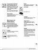
4 SECTION 5: GENERAL MAINTENANCE N Contents « Filling Fuel Tank * Crutch & Brake » Transport » Maintenance Schedule + Service Position » Drive Belt * Storage + Accessories « Engine Cooling « Chute Deflector « Engine Trouble Shooting General Maintenance Aries Dealers will provide any service which may be required to keep your unit operating at peak efficiency. Should engine service be required, it can be obtained from an Aries dealer or an authorized engine manufacturer's service center. .
Clutch AND BRAKE Impeller Control Cable Adjustment For Brake to function properly, there must ALWAYS be some slight, noticeable slack in the Control Cable Inner Wire when the Impeller Clutch Bail is disengaged (lowered position). This allows Extension Spring to pull Tidier Arm/Brake, braking Belt. Bail should travel 6-3/4 to cm) before contacting Handlebar.
Drive Beer To replace drive belt (Figure 13) 1. Remove Cowl and disconnect Extension Spring on Tidier Arm/Brake. 2. Remove Cap Screw and Washer from end of Impeller Shaft and pull off Impeller Drive Pulley. 3. Remove old Belt and install new one. 4. Replace pans in reverse order checking to be sure there is 1/32 to 1/16" (1-1.8 mm) clearance between Belt Finger and back side of Belt with Impeller Clutch Bail engaged.
MAINTENANCE SCHEDULE The chart below shows the recommended service schedule that should be performed on a regular basis. More frequent service may be required due to working conditions (heavy loads, high ambient temperatures, dusty conditions, airborne debris). See Engine maintenance instructions in Engine Manual. Maintenance SCHEDULE Service Performed Time interval Between Service 10 hours Check Fasteners ® Clean Air Intake and Cooling Sing ® Earrings Son-Thros Orig.
4 SECTION 5: SPECIFICATIONS CONTENTS ~~ » Specifications * Warranty Specifications 938008 938008 88522 88322E S8822E ne Power HP (KW) -2 6 (3.73 £ e Fast die 3800 4300 3600 (c¢] 8.46 (139} 8.0 (98, 8.46 (139 Fue! See Manual for and grade Fuel to Off Mix 80:1 Fuel Tank ity gt {Liters| 120141 Fuel Filter Sack Inside Dia. in (o 28{7.
~ ® QUALITY PRODUCTS QUALITY GUARANTEE PROTECTION PLAN an additional three years (36 months) thereafter, PURCHASER RESPONSIBILITIES * Maintenance & minor adjustments per ow tiers manta * Notification of need for warranty service » Transportation to/from place of warranty repair PRODUCT REGISTRATION + Return of registration card required to validate warranty PURCHASED COMPONENTS & NORMAL WEAR + Two year labor and parts on purchased components L&, {tractor drive train components manufactured by Dana, Eaton, F
Hardens 655 West Ryan Street « PC.