A SAFETY MESSAGE A The product for which you have requested information or sepia cement parts is not a current product. The replacement models incorporate product designs, sulfate features, safety Instructions or warnings which rep re.
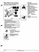
Your Satisfaction Is IMPORTANT engineered ta be the '.fish We have one Fundamental meas wed solely by price; durable, easy to-ties. mach me Questions? Please follow these helpful steps: 1. Always Refer to Your Perpetrator or Engine Manual First. a) Its detail will guide you through safe and proper operation and maintenance. b} it contains specifications on your model. ¢} If your questions are not answered in these manuals, go to step number two. 2.
4 TABLE OF CONTENTS e Son-THrRo Morels Model Number 924100 87824, 8 HP 24" Model Number 824101 87628, 9 HP 28" Mode! Number 924102 ST1032, 10 HP 32" Mode! Number 924103 871236, 12 HP 38" Model Number 924104 871028, 10 HP 28" Model Number 924105 8778, 8 HP Tractor Model Number 824106 871024, Section 1: INTRODUCTION The Manual Service and Replacement Parts Product Registration h ok Section 2: Savagery Safety Alert Symbol Signal Words Practices and Laws Required Operator Training .
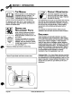
SECTION 1: INTRODUCTION The MANUAL 11800} Before operation of unit, carefully and A completely read your manuals. The sl contents will provide you with an understanding of safety instructions and controls during normal operation and maintenance. All reference to left, right, front, or rear are given from operator standing in operation position and facing the direction of forward travel.
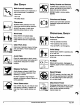
4 SECTION 2: SAFETY . Surety ALERT SYMBOL Whig is a safety alert symbol. [t means: « ATTENTION + YOUR SAFETY IS INVOLVED! When you see this symbol: + BECOME ALERT! + OBEY ITS MESSAGE! requiems Si Anal Corps The safety alert symbol is used with the signal words A DANGER, A WARNING and 4 CAUTION and colors 1o wafer you to safety messages. They-are used in safety decals on the unit and with proper operation and procedures in this manual. They alert you 1o the existence and relative degree of hazards.
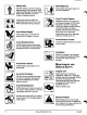
Surety Decals AND Location S ALWAYS replace missing or damaged Safety Decals. Refer to Figure 2 for Safety Decal locations. Figure 2 Ouijas onion 1. SAFETY INSTRUCTIONS oL Te avoid possible injury, read owner's manual and understand purpose of all safety alerts. * Allow operation only by properly trained adult, never children. » Stop engine and remove ignition key prior to leaving operator's position for any reason. *» Keep all controls, guards and safety devices properly serviced and functional.
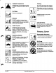
Unit Safety Walk Around Inspection Completes a walk around inspection of unit and work area to understand: « Work area * Your unit * Alt safety decals Clearances ALWAYS check overhead and side clearances carefully before operation. ALWAYS ba aware of traffic when operating along streets or curbs. Work Area Keep children and people away. Keep children out of work area and under watchful care of a responsible adult. Clear Work Area Keep.area of operation clear of all toys, pets, and debris.
E%?. [e[L A g Ambient Temperature ALWAYS allow unit and engine to adjust 1o outdoor temperatures before clearing snow. No Riders Never carry passengers. Reverse DO NOT operate in reverse unless absolutely necessary. ALWAYS backup slowly. ALWAYS look down and behind, before and while backing. Avoid Tip over Avoid uneven and rough terrain. DO NOT operate near disproofs, ditches, or embankments. Unit can suddenly tum over if a wheel is over the edge of a cliff or ditch, or if an edge caves in.
SRk @ X Safety Gear DO NOT operate unit without wearing adequate winter outer garments. Wear adequate safety gear, protective gloves. Wear proper footwear to improve footing on slippery surfaces. Protect eyes, face and head from objects that may be thrown from unit. Wear appropriate hearing protection, Avoid Sharp Edges Sharp edges can cut. Movement of parts can cut off fingers or a hand. Avoid Rotating Parts ALWAYS keep hands and feet away from all rotating parts during operation.
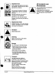
B2t Gus erg Explosive Fuel Suet Is highly flammable and its vapors are explosive. Handle with care. Use an approved fuel container. NO smoking, NO sparks, NO flames. ALWAYS allow engine to cool before Sudsy servicing. NEVER fill fuse tank when engine is running or hot from operation. NEVER fill or drain fuel tank indoors. Replace fuel cap securely and clean up spilled fusee, Replacement Parts ALWAYS maintain unit in sate operating condition.
4 SECTION 3: OPERATION Controls AND Feature S See Figure 3 for all Controls and Features locations. Dual Handle Interlock When Attachment Clutch and then Traction Drive Clutch are engaged, the Attachment Clutch will remain engaged {ever down) if released. To stop attachment, release Traction Drive Clutch and both cliches will disengage. Traction Drive Clutch Left Hand Lever Drive Squeeze the Traction Drive Disengage | Clutch Lever against the Handlebar to engage wheel drive for propelling unit.
Controls anp Features Locations 1. Traction Drive Crutch Lever 2. Attachment Clutch: Lever 3. Ignition Switch and Key 4. Primer Bulb : : 5. Choke 6. Throttle 7:Speed Selector " 8. Recoil Starter Handle 9. Deflector Remote Control 10. Chute Crank 11. Discharge Chute Deflector 12. Discharge Chute 13. Auger 14, impeller 15, Scraper Blade 186. Runner(s) 17. Headlight 18. Fuel Shut Off Valve SOSes Figure 3 o8 Orig.
Throttle The Throttle controls the engine speed. To increase or decrease the engine speed position control! by adjusting & ' 2. *Part-Throttle” (cold weather starts) 1. *Fast’ (normal or warm starts) iy 3. "Slow" oLz 4, "Stop” (engine is off) Speed Selector LOSS OF CONTROL could result in death or serious injury. DO NOT operate at high transport speeds on slippery surfaces. ALWAYS use care when backing. M CAUGHT OVER-SPEED can result in serious injury and/or damage to the unit .
Differential Lock Knob Differential Lock Knob is located on the left wheel hub. With differential hocked, power is applied equally to both wheels. To engage differential lock: * Pull and turn knob o "Locked" (1) position and release (knob will snap in place when positioned correctly). To resume differential action for transport: « Pull and turn knob to "Unlocked" (2) position and release. Scraper Blade IMPORTANT: DO NOT allow Scraper Blade to wear or Auger / Impeller housing will become damaged. Runners .
Runners THROWN OBJECTS can result in personal injury and/or property damage. On gravel surface, lower runners sa that housing will not pick up gravel. Check and adjust Runners (see Adjustments). Allow 1/8° {3mm} between scraper blade and hard, smooth surface(s). Allow (30mm}) between scraper blade an uneven surface(s). Function of Clutches FAILURE OF CLUTCHES OR BRAKES ray result in death or serious injury. Check crutch and brake function before each-use. Repair or adjust before operation.
mn IMMEDIATELY RELEASE BOTH CONTROL LEVERS TO STOP UNIT in an emergency. Stop Engine, remove Key and wait for & all rotating parts to stop before slaving operators position. & Loews. Release Traction Drive Clutch Lever and allow unit to-come 10 a complete stop. 2. .Engage and run Impeller a few minutes after use to prevent freeze-up of Impeller. 3.. Release Attachment Clutch Lever and wait for all moving parts to coma a complete stop. 4. Move Throttle to the "Snow" position. 5.
4 SECTION 4: GENERAL MAINTENANCE Aries Dealers will provide any service or adjustments To add fuel to Fuel Tank: ! ! ’ which may be required fo cheap your unit operating at 1. ALWAYS place unit in open or well ventilated area. peak efficiency. Should engine service be required, B contact an Aries dealer or an authorized engine 2. Stop engine and allow to cool. manufacturer's service center. 3. Clean Fuel Cap and surrounding area to prevent dirt from entering Fuel Tank (Figure 4). 4. Remove Cap.
Fuel Shut-off Valve IMPORTANT: The unit is equipped with a gravity feed type of fuel system. If the Fuel Shut-Off Valve is not in the closed "Of* position, gasoline can leak out of the carburetor while the unit is being transported. “The unit engine Fuel Shut-Off Valve has 2 positions: 1. Closed "Off" 2.
2. Rotate bat fingers out and away from belt and pulley by removing one cap screw and loosening the other. IMPORTANT. Uss care when rotating the belt fingers to prevent deformation of parts. NOTE: To gain clearance engage traction clutch and if necessary pull back attachment tidier arm clevis pin. 3. Replace traction drive belt and belt fingers In reverse order making sure pulleys align. if alignment is necessary, loosen engine populism set screws, reposition pulley and tightener set screws.
Shear Boers IMPORTANT: Use only Arlene Shear Sols for replacement, Use of any other type of shear bolt may result in severe damage to unit. ‘Occasionally a foreign object may enter the auger/ impeller housing and jam the auger, breaking Shear Bolt: which secure the auger to the shaft (Figure 8). This allows auger o tum freely on the shaft preventing damage o gar drive. S Auger Roll Pin Shear Bolt(s) Nut(s) P@n Figure 8 1. Cap Screw 2. Friction Wheel 3.
AN f Auger Gear case Cast Iron Oil Fill and Drain level plug Aries Special 1-2 Gear Lube Auger Gear case Aluminum BN Figure 10 o500 Lubrication. LOCATIONS HOT SURFACES can result in death or serious injury. DO NOT ouch parts which are hot from operation. ALWAYS allow parts to cool. IMPORTANT: Wipe each fitting clean before and after lubrication. IMPORTANT: DO NOT allow grease or oit 16 get on 1. Defector Chute 6. Pinion Chain friction wheel, drive disc of belts. 2. Auger and Shaft 7.
Deflector Remote Adjust.as required at clevis end and/or cap pivot cable end fitting, ‘ Runners Runners should be adjusted as conditions require. Raising nonflowering runners controls distance scraper blade {auger/impelier housing) is held above surface being cleared. 1. Position unit on a hard, flat, smooth level surface, 2. Adjust runners by inserting a spacer of desired thickness under center of scraper blade, loosen hardware, slide runners to flat surface (Figure 12).
2. Remove cotter pin and pull shift rod out of chassis until it stops, put speed selector jeer into reverse panel notch {Figure 14). Two notches are available, place in last notch (Figure 16). Last Reverse Notch Figure 16 1. Attachment Clutch 4. Adjustment Nut Cable 5. Speed Selector 2. Clutch Cable Spring Shift Rod 3. Traction Drive Clutch 6. Jam Nut Rod 7. Cotter Pin Figure. 14 cerium Drive Belt 2. Brake Shoe and Pad 8. 1/16" (1.
Keep all nuts, bolts and screws tight and know unit is in safe working condition. Check all hardware at regular intervals, Clean unit thoroughly and lubricate (see lubrication instructions). Touch up all unpainted areas to avoid rust ard sorta in a cool, dry protected area. IMPORTANT: NEVER spray unit with water or store unit outdoors to aid in prevention of rust or corrosion. Water can seep into sealed bearings, which are sealed against dint and debris only, causing reduced component life.
| | NO-THREW SPECIFICATIONS Mode Number 924100 924101 924102 224103 924104 924106 Description $T824 5T928 871082 871236 811028 8T1024 Engine Tecumseh Power Max Max Rotation Speed RPM 3600 Displacement cu. in. (oo} 198.43 (318.3) 21.82 (357.6) Electric Start 12V Key Start Optional Fuel See Engine Manual Tank Capacity ot {Liters} Snow Clearing Width in (cm) 24 (61.0) 24 (61.
{ PRODUCTS QUALITY GUARANTEE PROTECTION PLAN N LABOR an additional three years (36 months) thereafter, PURCHASER RESPONSIBILITIES + Maintenance & minor adjustments per yawners manual + Notification of need for warranty service + "Transportation to/from place of warranty repair PRODUCT REGISTRATION » Ream of registration card required to validate warranty PURCHASED COMPONENTS & NORMAL WEAR Le.
Hardens 855 West Ryan St rest » BO. Box 157 « Billion, W) 54110-0157 « 820-756-2141 » Fax $20-756-4421 Ask Your Dealer For Information On % These Other Fine Aries Products ’ *» Front and Rear Tine Tillers » Walk-Behind Lawn Mowers .