TABLE OF CONTENTS Section 1 - Introduction . . . . . . . . . . . . . . . . . 1.1 The Manual . . . . . . . . . . . . . . . . . . . . . . . 1.2 Service and Replacement Parts . . . . . . . 1.3 Product Registration . . . . . . . . . . . . . . . . 1.4 Unauthorized Replacement Parts . . . . . . 1.5 Disclaimer . . . . . . . . . . . . . . . . . . . . . . . . 1.6 Technical Service Communications . . . . . 1-3 1-3 1-3 1-3 1-3 1-3 1-3 Section 2 - Safety2-4 2.1 Safety Alerts . . . . . . . . . . . . . . . . . . . . .
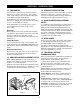
SECTION 1 - INTRODUCTION 1.1 THE MANUAL 1.3 PRODUCT REGISTRATION It is the purpose of this manual to provide complete instructions for service, maintenance, disassembly, repair, and installation of the mechanical components for the 927 Rear Engine Rider Mowers. A warranty registration card must be filled out, signed, and returned at the time of purchase. This card activates the warranty. Claims meeting requirements during limited warranty period will be honored.
SECTION 2 - SAFETY 2.1 SAFETY ALERTS 2.6 PREPARATION Look for these symbols to point out important safety precautions. They mean: Before starting any removal of parts, proper preparation is very important for efficient work. A clean work area at the start of each job will allow you to perform service repairs easily and quickly.
2.9 SAFETY RULES NO Flames! Allow engine to cool before servicing. NEVER fill fuel tank when engine is running, hot, or unit is indoors. Walk Around Inspection Complete a walk around inspection of unit and work area to understand: Abnormal Vibrations are a warning of trouble. Striking a foreign object can damage unit. Stop unit and engine. Wait for all moving parts to stop. Remove wire from spark plug. Inspect unit and make any necessary repairs before restart. • Work area. • Your unit.
Controls Come to a complete stop before reversing. Never jerk the control levers. Always use a steady even action to achieve smooth control. Always be aware of obstructions that may cause injury to operator or damage to the unit. Keep alert with eyes fixed in direction of travel. Maintenance ALWAYS maintain unit in safe operating condition. Damaged or worn out muffler can cause fire or explosion. Check the condition of the unit at the end of each day and repair any damage or defects.
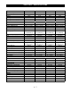
SECTION 3 - SPECIFICATIONS Model Number 927046 927047 927048 927049 Description Name RM 1028E RM 1132E RM 9028E RM 9030E 180 CCA 180 CCA 180 CCA 180 CCA Battery Brakes Drum Drum Drum Drum Gear & Pinion Gear & Pinion Gear & Pinion Gear & Pinion 26 (66) 26 (66) 26 (66) 26 (66) Front 4.10-3.50x4.00 4.10-3.50x4.00 4.10-3.50x4.00 4.10-3.50x4.00 Rear 16.6x5x8.00 16.6x5x8.00 16.6x5x8.00 16.6x5x8.
Model Number 927050 927051 927052 927053 Description Name RM 1232E RM 1332 RM 1330 RM 9028 Battery 180 CCA 180 CCA 180 CCA 180 CCA Brakes Drum Drum Drum Drum Gear & Pinion Gear & Pinion Gear & Pinion Gear & Pinion 26 (66) 26 (66) 26 (66) 26 (66) 4.10-3.50x4.00 4.10-3.50x4.00 4.10-3.50x4.00 4.10-3.50x4.00 Steering Turning Radius - in (cm) Tire Size Front Rear 16.6x5x8.00 16.6x5x8.00 16.6x5x8.00 16.6x5x8.
Model Number 927054 927055 927056 927301 Description Name RM 9030 RM 1332 RM 1330 RM 9028E Battery 180 CCA 180 CCA 180 CCA 180 CCA Brakes Drum Drum Drum Drum Gear & Pinion Gear & Pinion Gear & Pinion Gear & Pinion 26 (66) 26 (66) 26 (66) 26 (66) 4.10-3.50x4.00 4.10-3.50x4.00 4.10-3.50x4.00 4.10-3.50x4.00 Steering Turning Radius - in (cm) Tire Size Front Rear 16.6x5x8.00 16.6x5x8.00 16.6x5x8.00 16.6x5x8.
Model Number 927302 927303 927304 927305 Description Name RM 1228E RM 1232E RM 1328 RM 1332 Battery 180 CCA 180 CCA 180 CCA 180 CCA Brakes Drum Drum Drum Drum Gear & Pinion Gear & Pinion Gear & Pinion Gear & Pinion 26 (66) 26 (66) 26 (66) 26 (66) 4.10-3.50x4.00 4.10-3.50x4.00 4.10-3.50x4.00 4.10-3.50x4.00 Steering Turning Radius - in (cm) Tire Size Front Rear 16.6x5x8.00 16.6x5x8.00 16.6x5x8.00 16.6x5x8.
Model Number 927306 927307 927308 927310 Description Name RM 9028 RM 1328 RM 1332 RM 1028 Battery 180 CCA 180 CCA 180 CCA 180 CCA Brakes Drum Drum Drum Drum Gear & Pinion Gear & Pinion Gear & Pinion Gear & Pinion 26 (66) 26 (66) 26 (66) 26 (66) 4.10-3.50x4.00 4.10-3.50x4.00 4.10-3.50x4.00 4.10-3.50x4.00 Steering Turning Radius - in (cm) Tire Size - Front - Rear 16.6x5x8.00 16.6x5x8.00 16.6x5x8.00 16.6x5x8.
SECTION 4 - GENERAL MAINTENANCE & ADJUSTMENTS 4.1 CONTROLS AND FEATURES 4 5 3 6 CAUTION CA UTION Before starting engine be sure machine is in neutral and mower clutch is disengaged 2 P Depress clutch pedal and push latch to set. 7 WARNING TO AVOID SERIOUS INJURY OR DEATH Read operator's manual. Understand location and function of all controls. Look down and behind before and while backing. Remove objects thatcould be thrown by the blade. Avoid sudden turns.
4.2 SERVICE POSITIONS Ariens Dealers will provide any service or adjustments which may be required to keep your unit operating at peak efficiency. Should engine service be required, contact an Ariens dealer or an authorized engine manufacturer’s service center. WARNING: ACCIDENTAL ENGINE START UP can cause death or serious injury. ALWAYS stop engine, remove key, wait for moving parts to stop and remove wire from spark plug before adjusting or servicing. HOT SURFACES can result in death or serious injury.
4 3 5 2 6 1 1. 2. 3. 4. Steering Gear Adjustment Cap Screw Height Control Height Lever 5. View Quadrant Through Slot 6. Spring Clip Figure 5 Figure 4 4 3 4.5 MOWER BELT ADJUSTMENT Adjust mower belt after first five (5) hours of operation. To adjust 28" and 30" mowers (Figure 5): 6 1. Place height control lever in midnotch position, depress spring clip and tighten yoke on front of unit with a 3/4" socket wrench. 2 2.
3. Release parking brake and turn both rear wheels by hand. They should rotate freely in neutral (N) but not rotate with speed selector in any other position. 2 4. Using two 1/2" wrenches (to avoid twisting or distorting brake band), hold inner adjusting nut with one wrench and loosen outer lock nut with the other. 1 3 5. Turn rear wheel by hand while tightening inner adjustment nut until brake band just binds on hub. Back off adjusting nut by 1-1/2 turns and secure with locknut. 6.
Mower Pitch and Height Proper blade pitch is when the blade tip, measured from the bottom surface (Figure 10), is 1/4" to 3/8" (6.4 to 9.9 mm) lower at front of mower pan than when same tip is at rear of mower pan. 2 3 2. Slide lift strap and adjustment strap together to raise, or apart to lower rear of pan. 4.8 ANTI-SCALP ROLLERS Secure rollers in middle position for average lawn mowing. Front of Unit 1. 2. 3. 4. 1.
4.10 PINION AND STEERING ADJUSTMENT For ease of access to bottom of unit during service procedures, your unit may be driven up on ramps or tipped up onto bagger attachment service bar and braced securely. (For units without a bagger attachment, a service bar package is available through your Ariens Dealer.) On units with steering adjustment bracket, loosen lower lock nut and tighten adjustment nut until steering works smoothly with no play in gears. Tighten lower lock nut. 2 1 3 1.
SECTION 5 - ENGINE 5.1 ENGINE TROUBLESHOOTING The following troubleshooting chart is to be used to isolate engine problems and give possible causes and corrective action responses. TROUBLE Black Exhaust Blue/White Exhaust Difficult Starting Erratic Running Excessive Fuel Consumption High Oil Pressure Knocking Loss of Power or System Low Cranking Power Low Oil Pressure Misfiring Overheating Poor Compression Starts and Stops The troubleshooting key is generic and can be used for several types of engines.
NOTE: Run engine just prior to changing oil. Oil will flow more freely and carry away more contamination when warm. WARNING: Stop engine, remove key and wait for moving parts to stop before attempting any service procedures. 1. Drain engine crankcase by removing oil drain plug. After oil has drained, replace plug. 2. Remove oil fill cap and dipstick. CAUTION: DO NOT touch engine or riding mower parts which are hot from operation. Allow such parts to cool before servicing unit. 3.
5.5 SPARK PLUG 5.8 ENGINE REPLACEMENT Spark plug should be cleaned or replaced (if necessary) and gap reset to .030" every 100 hours of operation or yearly whichever comes first. 1. Remove debris from area around spark plug base. Consult parts manual to determine hardware used on replacement engine. NOTE: Depending on horsepower and manufacturer, various bolt patterns and amounts of hardware (taptites or cap screws) may be used to secure engine. 2. Remove spark plug from engine.
1 2 3 5 4 6 7 9 8 10 19 18 Figure 17 Briggs & Stratton Engine 11 Place washers between frame and engine at locations where cap screws will be installed. Using outer bolt circle secure engine to frame with four cap screws, washers and locknuts. 12 Torque to 125 in-lbs (7.7 Nm). NOTE: On Kawasaki engines torque cap screws to 18 ft-lbs (13.3 Nm). 17 13 14 16 1. Clip 2. Overflow Tube 3. Hose Clamp 4. Throttle Bracket 5. Throttle Lever 6. Throttle Brace 7. Link 8. Shield 9. Brace 10.Grommet 15 11.
SECTION 6 - MOWER DECK 6.1 ROTARY MOWER BELT REPLACEMENT 1. Disengage (OUT) mower clutch lever. 4 3 2. Loosen three nuts securing rear belt finger to back cover and rotate belt finger counterclockwise to remove from unit. 6 3. On 32" mowers, remove mower pulley belt finger, loosen cap screw on clutching idler and fixed idler to provide clearance for belt between belt fingers and idlers. 2 1 4. Remove old belt and place new belt in position on mower and engine pulley. 5 5.
3. Sharpen both ends of blade at original angle (25o), removing equal amounts of material from each end to maintain proper blade balance. New blades are balanced to within 1.3 in. oz. at factory. DO NOT grind around corner at tip of blade. If cutting edge of blade cannot be sharpened in a straight line to within 1/8 of an inch of its end, replace blade with Ariens replacement blade only. 6 4. Install blade, lock washer, and tighten hardware to torque listed above.
should not be greater than 3/16". If it is greater than 3/16" see your Ariens dealer to have it corrected. 1 3 8. To adjust cutting height, see Cutting Height and Mower Pitch and Height in the Adjustments section. NOTE: Lift strap is used for various diameters of mower pans and generally does not have to be adjusted. If replacing mower pan with that of a different diameter, refer to parts manual for correct front lift arm in conjunction with strap adjustment.
6.6 MOWER SPINDLE REMOVAL 1 1 19 28" to 30" Mower 18 17 32" Mower 2 13 20 3 15 14 16 13 12 4 5 21 11 6 7 9 10 8 1. 2. 3. 4. 5. 6. 7. Mower Pulley Belt Finger Plate Radial Bearing spindle Housing Spindle Shaft Bearing Slinger 8. Retainer Hub 9. Blade Tray 10.Mower Blade 11.Plate 12.Idler Arm with Brake 13.Washer 14.Bearing Spacer 15.Idler 16.Washer 17.Brake Band with Idler Arm 18.Fastener 19.Belt Finger 20.Idler 21.Idler Mount Figure 24 PA0210 1.
SECTION 7 - STEERING AND CONTROLS For ease of access to bottom of unit during service procedures, your unit may be driven up on ramps or tipped up onto bagger attachment service bar and braced securely. (For units without a bagger attachment, a service bar package is available through your Ariens Dealer.) 2. Remove cotter pin from front link on mower pan and disconnect link. Refer to Mower Pan section for removal of mower pan. 3. Remove cotter pin from drag link at tie rod arm and disconnect drag link. 4.
7.2 SPEED SELECTOR Disassembly of Carrier Carrier Assembly Removal 1. Remove cotter pin attaching shift link to bellcrank and disconnect shift link from bellcrank. 2. Remove spring from clutch shaft. 3. Remove cotter pin from one end of transfer shaft and remove transfer shaft from frame. 4. Unhook carrier yoke from clutch shaft and remove yoke and carrier assembly. 1. Remove locknut and thrust washer from top of spindle bolt. 2.
SECTION 8 - BRAKE AND CLUTCH 8.1 BRAKE DISASSEMBLY 8.2 CLUTCH AND BRAKE ADJUSTMENT 1. Remove cotter pin securing brake rod to brake lever 2. Remove nuts and washers securing brake band to brake lever. Clutch and brake adjustments are dependent upon each other. If depressing clutch and brake pedal fully does not stop riding mower and/or hold it on hill, brake must be adjusted. See section on Adjustments. 3. Remove cotter pin from pin securing brake lever to brake bracket. 4.
SECTION 9 - DRIVE TRAIN 9.1 REAR AXLE DISASSEMBLY 1. Remove wheel, hub cap, cotter pin, and retainer from short axle and remove short axle. 2. Remove roll pin in long axle and remove long axle along with washer on inside of axle. 3. Inspect all parts for wear or damage and replace as necessary. 4. Assemble in reverse order. 3 5 1 6 2 4 11 10 12 7 9 8 1 2 Figure 29 9.2 GEAR CASE REMOVAL 1. Remove wheel, cotter pin, spindle cup and hub cap from short axle and remove axle. 2.
9.1 GEAR CASE DISASSEMBLY 1 14 13 2 12 4 3 4 15 11 5 6 10 7 8 9 8 16 1. Ball Bearing 2. Breather 3. Cover 4. Needle Bearing 5. Pinion & Gear 6. Spacer 7. Idler Shaft 8. Ball Bearing 9. Pinion Shaft 10.Sleeve Bushing 11.Differential Assembly 12.Guard 13.Friction Wheel 14.Friction Wheel Hub 15.Lock Nut 16.Seal Figure 30 1. Remove locknut from friction disc hub and remove hub and woodruff key in pinion shaft. 2. Remove flange whizlock screws in cover and using slots provided pry cover off. 3.
Friction Wheel Wear Guide Figure 31 9 - 31
SECTION 10 - BAGGER 10.2 BAGGER ASSEMBLY WARNING: When operating on slopes, front weight accessory (P/N 727016) is recommended. Tip over or complete loss of steering may result from any combination of excessive bagger load, operation on slopes, abrupt turns and speed changes. 1 2 10.1 VANE INSTALLATION 3 Since vanes generally require more power and generate more, try bagging without vanes first. If performance is satisfactory, use bagger without vanes.
10.3 LOWER BOOT INSTALLATION 28" and 32" Mower Pans 28" and 30" Mower Pans Position lower boot so that the two rear pan clips are in line with the notches in the boot. Place boot in front pan clip. Rotate boot counterclockwise until rear pan clips are seated properly in boot notches. Secure boot with L-pin. Lift deflector, slide bottom edge of lower boot between runner and bottom edge of mower pan.
SECTION 11 - ELECTRICAL 11.1 SAFETY INTERLOCK SYSTEM In the RUN position, there should be no continuity between contacts "B" and "S". DANGER: Failure of interlock, together with improper operation of unit, could result in severe personal injury. If after performing the above checks the engine does not start, check interlock module by disconnecting it at connector. This removes the module from electronic ignition circuit, If engine starts, module is defective and must be replaced.
After cleaning, apply a thin coat of grease or petroleum jelly to terminals and cable ends, to retard corrosion. Reinstall battery. CAUTION: Connect positive (+) cable first, negative (-) cable last. discharged, a battery charger will be required for recharging. Before using a charger, an attempt can be made to recharge the battery using the engine alternator by jump starting the unit and allowing the to engine run.
Ariens Company 655 West Ryan Street P.O. Box 157 Brillion, WI 54110-0157 920-756-2141 Fax 920-756-2407 www.ariens.