Sno-Thro ® Operator’s Manual Manuel du Utilisateur Compact Series Models 920025 – Classic 24 (SN 000101 +) 920026 – Compact 20 (SN 000101 +) 920027 – Compact 24 (SN 000101 +) 920028 – Compact 24 Track (SN 000101 +) E10 ENGLISH FRANÇAIS 05135300 • 2/17 Printed in USA
TABLE OF CONTENTS WELCOME . . . . . . . . . . . . . . . . . . . . . . 1 SAFETY. . . . . . . . . . . . . . . . . . . . . . . . . 2 Practices & Laws . . . . . . . . . . . . . . . . . . Emission Control System. . . . . . . . . . . . Required Operator Training . . . . . . . . . . Safety Alert Symbol . . . . . . . . . . . . . . . . Signal Words . . . . . . . . . . . . . . . . . . . . . Safety Decals. . . . . . . . . . . . . . . . . . . . . Safety Rules. . . . . . . . . . . . . . . . . . . . . .
WELCOME Congratulations on your purchase and welcome to the Ariens family! Every snow thrower in the Ariens lineup is designed for long-lasting and unsurpassed performance. We are confident your machine will be part of your family for many years to come. Have Questions or Need Assistance? ariensstore.com • ariens.custhelp.com A service guide and a parts manual for your unit are available for free download or purchase at ariens.com.
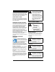
SAFETY WARNING: AVOID INJURY. This snow thrower is capable of crushing or amputating body parts. Failure to observe the safety instructions in the manuals and on decals could result in serious injury or death. ALWAYS disengage auger, stop unit and engine, remove key and allow moving parts to stop before leaving operator’s position. Read these safety rules and follow them closely.
4. Notice Safety Decal Descriptions NOTICE: Indicates information or procedures that are considered important but not hazard related. If not followed, property damage could result. 1. CAUTION! Danger! 5. Important IMPORTANT: Indicates general reference information worthy of special attention. SAFETY DECALS The safety decals on your machine are visual reminders of the important safety information in this manual. All messages on your unit must be fully understood and carefully followed.
SAFETY RULES 2. DANGER! The following safety instructions are based on the B71.3 specifications of the American National Standards Institute in effect at the time of production. Danger! Training ROTATING PARTS! Only use clean-out tool to clear blockages. NEVER use your hands. High-speed auger / impeller rotates below discharge opening. Wait for all moving parts to stop before removing clogs or servicing.
Handle fuel with care; it is highly flammable. • Use an approved fuel container. • Never add fuel to a running engine or hot engine. • Fill fuel tank outdoors with extreme care. Never fill fuel tank indoors. • Never fill containers inside a vehicle or on a truck or trailer bed with a plastic liner. Always place containers on the ground, away from your vehicle, before filling. • When practical, remove gas-powered equipment from the truck or trailer and refuel it on the ground.
Disengage attachment when not in use and when traveling from one work area to another. Maintenance and Storage Secure unit so it will not tip over during maintenance. Disengage power to the auger / impeller when snow thrower is transported or not in use. Before cleaning, removing clogs or making any inspections, repairs, etc., disengage clutch(es), stop engine, remove key, allow moving parts to stop and hot parts to cool.
Do not wear loose clothing or jewelry, and tie back hair that may get caught in rotating parts. NEVER attempt to unclog or clean unit while engine is running. Rotating auger / impeller can cause serious injury. When practical, remove gas-powered equipment from the truck or trailer and refuel it on the ground. If this is not possible, then refuel on a trailer with a portable container, rather than from a gasoline dispenser nozzle.
CONTROLS & FEATURES 18 10 15 25 14 24 23 22 17 16 3 7 21 20 12 26 11 19 6 1 13 1 2 8 4 9 5 Figure 3 1. 2. 3. 4. 5. 6. 7. 8. 9. 10. 11. 12. 13. Engine Key Primer Bulb Fuel Tank and Cap Fuel Valve Electric Start Button Choke Control Knob Oil Fill / Dipstick Oil Drain Recoil Starter Handle Speed Selector Lever Auger Impeller Shear Bolt (2) 14. 15. 16. 17. 18. 19. 20. 21.
SPEED SELECTOR LEVER WARNING: Read and understand the Safety section before proceeding. See Figure 7. Controls the speed of forward and reverse travel. See Figure 3 for all controls and features locations. 6 5 4 3 2 1 1 2 ENGINE KEY See Figure 4. Controls power to the engine. The key cannot be removed when in run position. Run Stop Figure 4 PRIMER BULB Adds fuel to engine for easier start on cold engines. Figure 7 FUEL VALVE See Figure 5. Controls fuel flow to the engine.
ATTACHMENT CLUTCH LEVER (RIGHT SIDE) See Figure 8. Controls auger / impeller movement. DUAL HANDLE INTERLOCK Allows auger / impeller to rotate without holding attachment clutch lever continuously. Auger continues to turn until both clutch levers are released. DISCHARGE CHUTE ROTATION LEVER See Figure 10. Rotates discharge chute left or right to control snow discharge. Figure 8 TRACTION DRIVE CLUTCH LEVER (LEFT SIDE) See Figure 9. Allows unit to travel forward and in reverse.
DISCHARGE CHUTE DEFLECTOR LEVER See Figure 11. Moves discharge deflector up or down to control height of snow discharge. Figure 12 Figure 11 OPERATION SCRAPER BLADE Contacts the surface being cleared and protects the housing from damage during normal use. SKID SHOE Controls the distance between the scraper blade and the surface. AXLE LOCK PIN Models 920025, 920026, 920027 Engages or disengages wheels with axle rotation, allowing for wheel drive or freewheeling. See Set Axle Lock Pin on page 12.
IMPORTANT: Use fresh unleaded fuel with an octane rating of at least 87. DO NOT use E85 blended fuels; the engine is not E20 / E30 / E85 compatible. The maximum recommended ethanol content is 10%. Ariens recommends using a quality fuel stabilizer in all fuel. See Short Term on page 27. 3. Engage attachment clutch. 3. Check engine oil level and add oil if needed. Refer to engine manual. 4. Check function of controls. • Attachment Clutch Lever • Traction Drive Clutch Lever • Dual Handle Interlock 5.
2. Run auger / impeller for a few minutes to remove loose or melting snow to prevent impeller from freezing. 3. Release attachment clutch lever. 4. Turn engine key to stop position and remove key. 5. Turn fuel valve to off position. For easier right turns: 1. Remove lock pin from right wheel hub. 2. Insert lock pin through outer axle hole. For easier left turns: 1. Remove lock pin from left wheel hub. 2. Insert lock pin through outer axle hole. CAUTION: One wheel MUST be locked with axle at all times.
CHECK DUAL HANDLE INTERLOCK Annually Every 25 hrs. Every 5 hrs. Service Performed Each Use MAINTENANCE SCHEDULE Check Clutch Lever Operation • Check Dual Handle Interlock • Check Fasteners • Check Clutch Cable Adjustments * • Check Tire Pressure • Check Track Tension Check Engine Oil 1. Stop engine. 2. Engage attachment clutch and then the traction drive clutch. 3. Release the attachment clutch lever. The attachment clutch should stay engaged until the traction drive clutch lever is released.
CHANGE ENGINE OIL LUBRICATE UNIT Refer to engine manual. Ariens recommends using Ariens Hi-Temp Grease or equivalent (see Service Parts) to lubricate fittings. Lubricate each season or every 25 hours of operation. CHECK AUGER GEARCASE OIL 1. Place unit on flat, level surface. 2. Remove oil fill plug and seal washer. See Figure 16. IMPORTANT: Wipe each fitting clean before and after lubrication. Remove Bottom Cover IMPORTANT: DO NOT remove gearcase cover. Models 920025, 920026, 920027 1.
Traction Drive 3 1. Lubricate as shown in Figures 18, 19, 20 and 21. 6 IMPORTANT: DO NOT allow grease or oil to contact friction disc, friction plate or belts. 2. Reinstall bottom cover and return unit to operating position. 2 Models 920025, 920026, 920027 * 5 4 1 * 1. 2. 3. 4. 5. 6.
Model 920028 * Figure 22 Figure 20 ADJUSTMENTS Model 920028 WARNING: AVOID INJURY. Read and understand the Safety section before proceeding. * ADJUST SCRAPER BLADE The auger housing may be damaged if blade wears down too much. 1. Tip unit back onto handlebar, support auger housing and loosen nuts retaining blade. 2. Lower blade and tighten nuts. 3. Adjust skid shoes. See Adjust Skid Shoes on page 17.
ADJUST DISCHARGE CHUTE DEFLECTOR LEVER See Figure 25. If deflector does not stay in selected position, tighten the nut under the control panel. 3 1 2 1. Scraper Blade 2. Spacer 3. Skid Shoe Figure 23 REPLACE SHEAR BOLTS IMPORTANT: Ariens recommends using only Ariens OEM shear bolts when replacing shear bolts. See Figure 24. 1. Align shear bolt holes in auger with shear bolt holes in the shaft. 2. Insert bolts through holes. 3. Secure bolts with nuts. 4. Tighten bolts to 7.9 – 16.5 N•m (5.8 – 12.
ADJUST SPEED SELECTOR LEVER 1 2 3 1. Chute Cable 2. Upper Adjustment Nut 3. Lower Adjustment Nut Figure 26 ADJUST DISCHARGE CHUTE See Figure 27. If discharge chute does not stay in selected position, tighten nut on carriage bolt. See Figure 28. 1. Disconnect adjustment pivot pin from speed selector arm. Save hardware for reinstallation. 2. Position speed selector lever in fastest forward position. 3. Turn speed selector arm down as far as it will go. 4.
1 4 2 2 1 3 1. 2. 3. 4. 3 Shift Rod Adjustment Pivot Pin Speed Selector Arm Hairpin Figure 28 1. Attachment Clutch Cable 2. Cable Adjustment Barrel 3. Jam Nut Figure 29 ADJUST ATTACHMENT CLUTCH & BRAKE 5. With the attachment clutch disengaged, make sure auger idler arm lightly touches the frame. See Figure 30. WARNING: AVOID INJURY. Improper adjustment could result in unexpected movement of auger and impeller causing death or serious injury.
Check Attachment Idler Arm Roller Clearance 1. Place unit in service position and remove bottom cover. See Remove Bottom Cover on page 15. 2. Engage attachment clutch and check the clearance between the frame and plastic roller on the lower end of the attachment idler arm. Roller should be 12.7 – 22.2 mm (1/2 – 7/8") from the frame. See Figure 31. 2 1 1. Attachment Belt Idler 2. Idler Adjustment Nut Figure 32 Check Attachment Brake 1 1. Attachment Idler Arm Roller 2.
ADJUST TRACTION DRIVE CLUTCH See Figure 35. If unit does not drive correctly, adjust traction clutch to compensate for friction disc wear. 1. Stop engine, remove key and wait for all moving parts to stop and for hot parts to cool. 2. Disconnect spark plug wire. 3. Loosen jam nut on traction cable adjustment barrel, and then turn adjustment barrel down to shorten cable and remove cable slack. 2 1 1 1. Brake Pad 2. Attachment Pulley Figure 33 2 3 Measure here. Check Belt Finger Clearance See Figure 34.
Adjust here. 1 1. Swing Gate Tab 2. Stop Hole Figure 36 Figure 38 If unit does not travel correctly, adjust track tension. See Figure 38. • If unit pulls to the left, tighten the left track adjuster. • If unit pulls to the right, tighten the right track adjuster. 2 5. Reconnect spark plug wire. ADJUST TRACK TENSION Model 920028 1. Check tension by applying pressure to track between the upper and rear track rollers. Deflection should be approximately 9.5 mm (3/8"). See Figure 37. Apply pressure here.
ADJUST HEIGHT-ADJUSTMENT CABLE Model 920028 See Figure 39. NOTICE: Make sure height adjuster lock finger is fully engaged before making adjustments. 1. Loosen jam nuts on cable adjustment barrel. 2. Tighten right jam nut to remove slack between adjustment barrel and cable eyelet. 3. Tighten left jam nut. 1 6 1. 2. 3. 4. 5. 6.
TROUBLESHOOTING Problem Probable Cause Engine key in stop position. Choke is off. Fuel valve is closed. Fuel tank is empty. Engine is not primed. Correction Turn engine key to run position. See Engine Key on page 9. Turn choke control knob to on position. See Choke Control Knob on page 9. Open valve. See Fuel Valve on page 9. Fill tank with fuel. See Before Operating Unit on page 11. If engine is cold, press primer bulb three times and start engine. Do not prime a warm engine. See Primer Bulb on page 9.
TROUBLESHOOTING Problem Probable Cause Shear bolts are broken. Attachment clutch / brake is not adjusted correctly. Impeller is frozen in place. Ice or debris is obstructing auger. Correction See Replace Shear bolts on page 18. See Adjust Attachment Clutch & Brake on page 20. Move unit to a warm place to thaw. Stop engine, remove key and wait for moving parts to stop. Check for and remove obstruction before restarting.
STORAGE WARNING: AVOID INJURY. Read and understand the Safety section before proceeding. SHORT TERM 1. Run auger / impeller for a few minutes to remove loose or melting snow and prevent impeller from freezing. 2. Tighten all hardware to correct specifications. 3. Inspect unit for visible signs of wear or damage. Repair as needed. 4. Apply a light layer of oil or anti-rust compound on bare metal areas. 5. Prepare fuel system for storage. NOTICE: Ariens recommends using a quality fuel stabilizer in all fuel.
SPECIFICATIONS Model Number 920025 Description Engine Gross Torque* – N•m (lb-ft) 3 3 Displacement – cm (in ) 920026 920028 Classic 24 Compact 24 Compact 20 Compact 24 Track Ariens AX208 120V Ariens AX223 120V/60W 12.9 (9.5) 13.6 (10.0) 208.0 (12.7) 223.0 (13.6) Maximum RPM – No load 3600 ± 100 Electric Start 120V Fuel Tank Capacity – liter (qt) Headlight 920027 1.4 (1.5) N/A 20 Watt Chute Chute Rotation Angle 205° Rotation Control 2.
Sno-Thro®, Sno-Tek® and Chore Performing Equipment Limited Warranty Warranty Ariens Company (Ariens) warrants to the original purchaser that Ariens, Gravely, Parker, and Countax ® ® brand chore performing equipment (including Sno-Thro and Sno-Tek equipment) purchased on or after 1/1/2016 will be free from defects in material and workmanship for the time period noted in the chart below.
Exceptions and Limitations The chart below details special exceptions to this warranty: Warranty Code Warranty Period Use 1 Year All None Commercial These components are not covered when used commercially. Maximum 2 Years All Warranty is limited to 2 years for consumer use. (1 year for warranty code "PD".) Except as noted above, these components are covered for defect, not for wear. Maximum 2 Years All Warranty is limited on idlers to 2 years for consumer use.
Exclusions – Items Not Covered by This Warranty • Parts that are not genuine Ariens, Gravely, Parker or Countax service parts are not covered by this warranty and may void the warranty. • Damages resulting from the installation or use of any part, accessory, or attachment which is not approved by the Ariens Company for use with product(s) identified herein are not covered by this warranty.
655 West Ryan Street Brillion, WI 54110 ariensstore.com ariens.custhelp.com parts.ariens.