
Instructions / Assembly


07900223 • 1/17 • Page 6 of 9
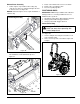
14. Insert ROPS tube (item 1) through the opening and
between right support bracket and frame. Ensure that
hinge plates are positioned facing the rear. See
Figure 18.
15. Attach ROPS with two 1/2 x 3" hex bolts (item 6) and
two 1/2" center-lock flange nuts (item 11). DO NOT
fully tighten hardware at this time. See Figure 19.
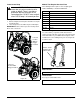
Assemble ROPS Hardware
1. Install two anti-vibration bumpers (item 7) in ROPS
tube hinge plates and retain with two 5/16 x 2 9/16"
pins (item 8) and two 5/16" E-rings (item 9). See
Figure 20.
2. Attach lock pin (item 12) to hinge plate with 1/4 x 1/2"
hex washer head screw (item 13). See Figure 21.
3. Repeat steps 1 and 2 for second tube.
Figure 18
1
Figure 19
6
11
Figure 20
7
8
9
Figure 21
12
13