Walk Behind Lawn Mower Owner/Operator Manual Models 911110 - P 21LM 911111 - SP 21LM 911112 - DSP 21LM 911113 - DESP21LM ENGLISH FRANÇAIS ESPAGNOL Transfer model & serial number label from product registration here. Coller l’autocollant du modèle et du numéro de série dans cet encadré. Transferir aquí la etiqueta del modelo y número de serie del registro del producto.
TABLE OF CONTENTS Safety . . . . . . . . . . . . . . . . . . . . . . . . . . . 3 Storage . . . . . . . . . . . . . . . . . . . . . . . . . 23 Assembly . . . . . . . . . . . . . . . . . . . . . . . . 8 Troubleshooting . . . . . . . . . . . . . . . . . 23 Controls and Features . . . . . . . . . . . . 10 Service Parts . . . . . . . . . . . . . . . . . . . . 24 Operation . . . . . . . . . . . . . . . . . . . . . . . 11 Accessories . . . . . . . . . . . . . . . . . . . . . 24 Maintenance. . . . . . . . .
DISCLAIMER 4. Explain recommended lubrication and maintenance. Advise customer on adjustments. Remind customer to change oil in 4 cycle engine crankcase after first five (5) hours of operation. 5. Instruct customer on controls and operation of unit. Discuss and emphasize the Safety Rules. Give customer Owner/Operator, Parts, and Engine manuals. Advise customer to thoroughly read and understand them.
SAFETY DECALS AND LOCATIONS Keep safety devices (guards, shields, switches, etc.) in place and working. ALWAYS replace missing or damaged safety decals. Refer to Figure 2 for safety decal locations. OL3030 Go across slopes, not up and down. 1 Look down and behind before and while moving backward. Do not park on a slope unless chocked or blocked. 3 Do not allow operation of machine by untrained personnel. 2.
If the operator or the mechanic cannot read the manual, it is the owner’s responsibility to explain it to them. Only the user can prevent and is responsible for accidents or injuries occurring to themselves, other people or property. ALWAYS remove key (if equipped) and disconnect wire from spark plug before assembly. Unintentional engine start up can cause death or serious injury. Complete a walk around inspection of unit and work area to understand: • work area • your unit • all safety decals.
Stop engine before removing and emptying grass bag. When mulching or bagging, ALWAYS install discharge cover. When side discharging, ALWAYS install side discharge deflector. ALWAYS shut off engine, allow blade to stop and disconnect spark plug wire before clearing clogs or cleaning unit. Check grass bag for wear, damage, and/or deterioration. Replace only with Ariens original equipment replacement parts for safety.
Charge batteries in an open, well-ventilated area, away from spark and flames. Unplug charger before connecting or disconnecting battery. Wear protective clothing and use insulated tools. Accidental engine start up can cause death or serious injury. Except where specifically recommended, ALWAYS stop engine, remove key (electric start models), wait for moving parts to stop, allow parts to cool and disconnect spark plug wire before inspecting, servicing, adjusting or repairing unit.
ASSEMBLY ASSEMBLY CAUTION: AVOID INJURY. Read and understand the entire Safety section before proceeding. CARTON CONTENTS 1 1. Remove mower and handlebar from carton. 2. Install the handlebars on the pivot pins attached to the handlebar uprights. NOTE: Make sure the cables (connected to the handlebar) are on the left side of the unit. 3. Remove the handlebar mounting hardware from the handlebar uprights. 4.
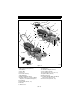
6. Connect the engine/blade control cable to the engine. Route the z-bend cable end into engine shutoff lever as shown below. Insert the cable connector into the cable mounting bracket on the engine. Make sure the connector snaps into place securely. 911110, 111 7. Fill engine crankcase with oil. See engine manual. 8. Set-up mower for bagging, side discharge or mulching. See MOWER SET-UP on page 14. NOTE: Bagging is not standard on push models. See ACCESSORIES on page 24 for kit part numbers. 9.
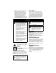
CONTROLS AND FEATURES 21 18 17 19 3 20 2 1 6 4 22 5 3 9 16 18 9 4 6 17 7 13 7 12 8 5 10 9 9 8 9 10 15 11 13 12 9 14 Figure 6 1. Engine/Blade Control (911110, 111) 2. Wheel Drive Control (911111) 3. Handlebars 4. Grass Bag 5. Rear Door 6. Fuel Tank and Cap 7. Oil Fill/Dipstick 8. Muffler and Muffler Guard 9. Cutting Height Levers (2 Rear Wheel Adjusters, 2 Front Wheel Adjusters) 10. Lift Handle 11. Primer Bulb (911110, 111) 12. Air Filter 13. Mulch Cover OM1866 14.
OPERATION CONTROLS AND FEATURES 911112, 113 See Figure 6 for locations. STOP WARNING: Improper operation can lead to injury. Learn what the controls do and how they work. Thoroughly read and understand entire Operator Manual. CAUTION: AVOID INJURY. Read and understand the entire Safety section before proceeding. Engine/Blade Control START and RUN CAUTION: Check function of Engine/Blade Control regularly. Improper function of control could cause injury.
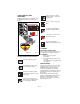
OPTIONAL CONTROLS Cutting Height Settings Chart Cut grass length Primer Bulb (911110, 111) 1 1" (25 mm) 2 1-1/4" (32 mm) Push the primer bulb in to add fuel for easier engine start. 3 1-1/2" (38 mm) 4 2-1/4" (57 mm) 5 2-3/4" (70 mm) 6 3-1/2" (89 mm) 7 4" (102 mm) Notch Wheel Drive Control (self-propelled models) CAUTION: Unit will move forward at engine start if wheel drive control is engaged. ALWAYS release wheel drive control before starting unit.
911112, 113 Fuel shutoff valve open. To drive forward: Slowly pull the wheel drive control toward you until you reach a comfortable ground speed. Hold the wheel drive control in this position to maintain the speed. To stop: Release wheel drive control. Fuel shutoff valve closed. Choke Control (91112, 113) Move choke lever to the choke position to start a cold engine.
MOWER SET-UP 1 CAUTION: DO NOT operate mower unless either side discharge cover or side discharge deflector is installed. Thrown objects may cause damage or injury. Never operate unit with rear door open unless grass bag is in place. CAUTION: If clog or obstruction prevents grass flow, release engine/blade control and disconnect spark plug wire before attempting to clear away any clogs. 3 2 4 To Bag (Optional on Push Models) CAUTION: Check grass bag frequently for wear or deterioration.
2 1 1 2 1. Side Discharge Chute 2. Knob 3 3. Mulch Cover 1. Mulch Plug 2. Rear Door Figure 13 Figure 12 To Mulch EMERGENCY STOPPING See Figure 13 on page 15. 1. Shut off unit. 2. Remove grass bag and side discharge chute, if installed. 3. Make sure mulch cover is closed and secured with knob. 4. Lift rear door and insert mulch plug with the beveled face to the left. There should be no openings between mulch plug and mounting surface of the deck. 5. Close rear door. NOTE: Rear door must close flush.
STARTING AND SHUT OFF Shut Off 1. Release wheel drive control and allow unit to stop completely (self-propelled models). 2. Release engine/blade control. 3. Turn key to off position and then remove key (electric start models). WARNING: Improper operation can lead to injury. Learn what the controls do and how they work. Thoroughly read and understand entire Operator Manual. See Figure 6 for all Controls and Features. NOTE: Start engine on a level surface that is free of debris. Manual Start 1.
MAINTENANCE CHECK WHEEL DRIVE CONTROL (self-propelled models) CAUTION: AVOID INJURY. Read and understand the entire Safety section before proceeding. Ariens Dealers will provide any service, parts or adjustments which may be required to keep your unit operating at peak efficiency. Should engine require service, contact an Ariens Dealer or an authorized engine manufacturer's service center.
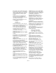
Sharpen the Mower Blades 3. Check mower blade balance. Slide mower blade on an unthreaded bolt. A balanced blade should remain in a horizontal position. If either end of mower blade moves downward, sharpen the heavy end until blade is balanced (Figure 15). 4. Install mower blade on unit. 5. Tighten the bolts to a torque of 37.5 50 lbf-ft (51-68 N•m). CAUTION: DO NOT sharpen mower blades while on unit. An imbalanced mower blade will cause excessive vibration and eventual damage to unit.
CHECK SPARK PLUG CHECK MUFFLER Spark plug should be replaced every 100 hours of operation or each year. NOTE: Loose spark plug wire terminals can cause sparking. Replace terminal if damaged. Check muffler for debris, cracks, wear, or other damage. CAUTION: Replace worn-out mufflers immediately. Continued use could result in fire or explosion. CHECK ENGINE COOLING WARNING: HOT SURFACES can cause death or serious injury. DO NOT TOUCH parts which are hot from operation. ALWAYS allow parts to cool.
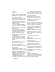
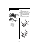
DRIVE BELT REPLACEMENT 1 (self-propelled models) 2 To remove drive belt: 1. Disconnect spark plug wire from spark plug. 2. Remove transmission cover. 3. Disconnect idler return spring from idler arm. See Figure 17. 4. Disconnect the wheel drive cable from transmission mount, and then disconnect drive cable spring from idler arm. 5. Remove belt from transmission input pulley and transmission idlers, and then push the belt out through the belt channel. 6. Put the unit in the service position.
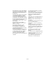
2. Connect the wheel drive cable spring to the idler arm as shown in Figure 20, and then connect the wheel drive cable to the transmission mount. See Figure 17. NOTE: Unit comes equipped with a maintenance-free battery that requires no regular maintenance except cleaning the terminals. To Remove Battery from Unit 1. Disconnect negative (–) cable first, then positive (+) cable (Figure 21). 2. Remove battery cover and battery. Save mounting hardware for reinstallation. To Replace Battery on Unit 1.
To increase traction and speed, move the cable adjuster down the handlebar. To decrease traction and speed, move the cable adjuster up the handlebar. 2. Check the adjustment and readjust as needed. Connect battery charger here. Figure 22 WHEEL DRIVE CONTROL ADJUSTMENT (self-propelled models) See Figure 23. NOTE: The unit should stop immediately when the wheel drive control is released, and the unit should not creep forward when the wheel drive control is disengaged with the engine running.
STORAGE Inspection CAUTION: AVOID INJURY. Read and understand the entire Safety section before proceeding. IMPORTANT: NEVER spray unit with highpressure water or store unit outdoors. Store mower in a cool, dry, protected location. Inspect mower and repair or replace worn or damaged parts to avoid delays when beginning use again. Regularly check all hardware and keep fasteners tight. Know unit is in safe working condition. Cleaning Grass Bag Allow unit to cool.
PROBLEM PROBABLE CAUSE Wheel drive does not engage (SelfPropelled models) CORRECTION 1. Wheel drive control not engaged. 2. Drive belt out of position. 1. Engage wheel drive control. 2. Check drive belt. Adjust as necessary (see CHECK DRIVE BELT (self-propelled models) on page 18). 3. Replace belt (see CHECK DRIVE BELT (self-propelled models) on page 18). 4. Check wheel drive control cable. Adjust or replace as needed. See CHECK WHEEL DRIVE CONTROL (self-propelled models) on page 17. 5.
SPECIFICATIONS Model Number Description Length - in. (cm) Height - in. (cm) Width - in. (cm) Actual Weight - lbs (kg) Cutting Width- in. (cm) Cutting Height - in. (cm) Engine, 4 cycle Model Trim Engine Power - HP (kW) @ Max. RPM Max Rotation Speed of Cutting Edge RPM (min-1) Governed RPM (May be different from maximum rpm.) Displacement Cu. In. (cc) 911110 P21LM 69 (31.3) 911111 911112 SP21LM DSP21LM 70 (177.8) 47 (119.4) 21.5 (54.6) 83 (37.6) 97 (44.0) 21 (53.3) 21 (53.3) 21 (53.3) 21 (53.
Ariens Limited Warranties 2-Year Limited Lawn and Garden Consumer Warranty Ariens Company (Ariens) warrants to the original purchaser that Ariens and Gravely brand consumer products manufactured by Ariens Company will be free from defects in material and workmanship for a period of two (2) years after the date of purchase, and that Ariens will repair any defect in material or workmanship, and repair or replace any defective part, subject to the conditions, limitations and exclusions set forth herein.
Exceptions, Limitations, Exclusions These warranties are subject to the following conditions, limitations, and exclusions: The following items are excluded from this To obtain warranty service, the following warranty: conditions must be met: • Engines and enty and are not covered by this • The purchaser must perform the warranty. maintenance and minor adjustments • Hydro-Gear transmissions and/or explained in the owner’s manual.
Ariens Company 655 West Ryan Street P.O. Box 157 Brillion, WI 54110-0157 920-756-2141 Fax 920-756-2407 www.ariens.