Zoom ® Owner/Operator Manual Models 915107 - 2450 915105- 2150 915103- 1840 915101 - 1634 02997700B 2/08 Printed in USA
ii q-'_:] 1:1 [o]_ [_o] _/ / :1_/ i_'] SAFETY ......................... ASSEMBLY ....................... 3 STORAGE 9 TROUBLESHOOTING ...................... CONTROLS AND FEATURES ....... 11 SERVICE OPERATION ..................... 12 ACCESSORIES 15 SPECIFICATIONS 17 WARRANTY MAINTENANCE SCHEDULE ........ SERVICE AND ADJUSTMENTS ..... II_II II=To]_Ir=_l_o] THE MANUAL ............. PARTS ................. .................. ................ .....................
DELIVERY 2. Understand all Safety Precautions provided in the manuals. 3. Review control functions and operation of the unit. Do not operate the unit unless all controls function as described in this manual. Customer Note: If you have purchased this product without complete assembly and instruction by your retailer, it is your responsibility to: Read and understand all assembly instructions in this manual.
NOTATIONS CAUTION: POTENTIALLY HAZARDOUS SITUATION! Ifnot avoided, MAY RESULT inminor ormoderate injury. Itmayalsobe used toalertagainst unsafe practices. NOTE: General reference information for proper operation and maintenance practices. IMPORTANT: Specific procedures or information required to prevent damage to unit or attachment. SAFETY DECALS AND LOCATIONS ALWAYS replace missing or damaged Safety Decals. Refer to figure 2 for Safety Decal locations.
_ "/_" Always stand clear of discharge area. Do not direct discharge toward other people. Never carry children. D_LI_t while Keep operating. people away from unit OL1806 Go up and down slopes, not across. Shut off engine, remove key, and read manual before you adjust or repair unit. ©L1807 ©L1812 DO NOT operate on slopes over 10 °. If machine stops going uphill, stop blade and back down slowly. Avoid sudden turns. NO STEP! Always keep feet away from rotating parts.
&DANGER! Avoid uneven or rough terrain. DO NOT operate near drop-offs, ditches, or embankments. Unit can suddenly turn over if a wheel is over the edge of a cliff or ditch, or if an edge caves in. Keep hands and feet away. Dust, fog, etc. can reduce vision and cause an accident. Operate unit only when there is good visibility and light. _L--------_-_ Do not operate mower unless guards are in operating position or bagger is attached.
NEVER direct discharge towards persons or Use extra care while operating machines with property. Thrown objects mayricochet back grass catcher or other attachments. They can towards operator. ALWAYS stand clear ofthe affect stability of the machine. discharge area. Avoid starting, stopping, or turning on a ALWAYS disengage attachment, stopunit slope.
NEVER fillcontainers inside avehicle orona DONOT change engine governor settings or truck ortrailer bedwithaplastic liner. Always over-speed engine. place containers ontheground away from Fumes from engine exhaust cancause injury yourvehicle before filling. ordeath. DONOT runengine inanenclosed When practical, remove gas-powered area. Always provide good ventilation. equipment fromthetruck ortrailer andrefuel ALWAYS maintain unitinsafeoperating itontheground. Ifthisisnotpossible, then condition.
Check Tire Pressure Read andunderstand theentire WARNING: AVOID INJURY. CAUTION: Avoid injury! Explosive separation of tire and rim parts is possible when they are serviced incorrectly: Do not attempt to mount a tire without the proper equipment and experience to perform the job. Do not inflate the tires above the recommended pressure. Do not weld or heat a wheel and tire assembly. Heat can cause an increase in air pressure resulting in an explosion. Welding can structurally weaken or deform the wheel.
Check function of all controls See OPERATION on page 12. 1. Steering Lever 2. Seat 3.
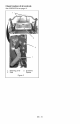
[_o]_ij_[o_ P'__I m]I_1_i uL_"] 7 8 11 915107 10 1 9 4 915105,103,101 Figure 4 1. Throttle Lever 2. Choke Control 3. Ignition Switch 4. PTO Switch 5. Seat 6. 7. 8. 9. Steering Levers Fuel Tank Mower Lift Pedal Mower Deck 10. Discharge Chute 11.
[o]-J:1_l:t / [o]_ Safety Interlock System Read and understand the entire WARNING: AVOID INJURY. Safety section before proceeding. ,_ WARNING: Safety interlock failure and improper operation of unit can result in death or serious injury. Check system before each use to make sure it is functioning properly. CONTROLS AND FEATURES See figure 4 for all controls and features locations. Perform the following tests to ensure the safety interlock system is working properly.
Power Take-Off (PTO) Switch Engages (2) and disengages (1) mower blades. o Steering 3 2 1 Levers Reverse (1)backward. Pull both steering levers Mower Lift Pedal Forward (2) - Push both steering levers forward. Left (3) - Pull left steering lever back or push right steering lever forward or a combination of both. Right (4) - Pull right steering lever back or push left steering lever forward or a combination of both. 2. Adjustment Hole 3.
STARTING AND SHUTTING OFF ENGINE FOR BEST PERFORMANCE Starting Keep mower blades sharp. Cut grass when it is dry. the Engine Keep mower deck properly leveled. NOTE: Disengage the PTO, engage the parking brake, and place the steering levers in neutral prior to starting the engine. 1. If the engine is cold, move the choke control to the On position. If the engine is warm or hot, do not use choke. Do not set height of cut too low. For very tall grass, mow twice. Do not travel too fast.
_l,]:i WARNING: AVOID INJURY. Read and understand the entire Safety section before proceeding. __Jl:l IMPORTANT: Proper maintenance can prolong the life of unit. The following chart shows the recommended service schedule. Refer to the maintenance instructions in the Engine Manual for additional information. NOTE: To have full access to the engine, the seat must be tipped forward (see TIPPING SEAT FORWARD on page 17) and the hood opened (see MOWER DECK REMOVAL AND INSTALLATION on page 17).
Interval Task Each Use Follow Action Engine Manual Maintenance Schedule 25 Hours Check or Every Season Battery Lubricate Unit 50 Hours or Every Season 100 Hours Check Fasteners or Every Season Check All Belts Keep battery and battery terminals Battery Cables on page 21 ). Apply grease to zerk (1) on each front wheel Check mower blade mounting hardware and all other fasteners. Replace fasteners that are missing or damaged. Tighten all nuts and bolts to the correct torque value.
__1 r_,!_ Im3 r_,1m]lll_'_lII_N:1_III__] MOWER DECK REMOVAL AND INSTALLATION ,_ Read and understand the entire WARNING: AVOID INJURY. Safety section before proceeding. TIPPING SEAT FORWARD Put steering levers up and tip seat forward (figure 7). Remove (Figure 8) 1. Remove PTO belt from electric clutch (see REPLACING PTO BELT on page 23). NOTE: Perform step 2 and 3 for the right and left side of unit. 2. Remove drag link from mower deck. 3. Remove front and rear trunnions from lift arms. 4.
Install (Figure 8) 1. Slide mower deck under unit. 3. Install drag link on mower deck. 4. Install PTO belt on electric clutch (see REPLACING PTO BELT on page 23). 5. Level and adjust pitch of mower deck (see LEVELLING AND ADJUSTING PITCH OF MOWER DECK on page 18). NOTE: Perform step 2 and 3 for the right and left side of unit. 2. Install front and rear trunnions on lift arms. 1. 2. 3. Rear Trunnion PTO Belt Mower Deck 4. 5. 6.
The Forward Lowest Cutting Position 3 1 Blades 2 Pitch Of The Mower (Figure 10): Should be 0.0 in. (0.0 mm) to 1!4 in. (6.35 mm) pitched forward. NOTE: This measurement must be taken when the mower blades ends are facing forward. Forward Pitch of Mower Blades 3 1-1/2 in. + 1/4 in. (3.8 cm +0.64 Highest Cutting 1 2 cm) Position 1 2 Front of Mower Deck 1. Mower Deck 2. Mower Blade 4-1/2 in. + 1/4_n. (11.4 cm + 0.64 cm) 1. 2. Mower Deck Mower Blade 3. 3.
REPLACING MOWER BLADE Adjusting The Mower Deck To Adjust Mower Blade Height And Pitch (Figure 12): Remove (Figure 13) NOTE: Adjusting the mower deck will adjust he height and pitch of the mower blades. 1. Adjust the trunnions first and re-take the three measurements required to level and adjust the pitch of the mower deck. These measurements are: a. The distance from the mower CAUTION: Mower blades are sharp and can cut you. Wrap the blades or wear gloves, and use extra caution when servicing them.
1.Remove mower blade from unit(see REPLACING MO WER BLADE on page 20). Ariens recommends having mower blades sharpened by a professional. Contact your Ariens dealer. WARNING: Battery posts, terminals and related accessories contain lead and lead compounds, chemicals known to the State of California to cause cancer and reproductive harm. Wash hands after handling. Discard mower blade if (figure 13): more than 1/2 in. (1.27 cm) of metal is removed. the air lift erosion area is eroded.
ADJUSTING STEERING 3.Clean battery cable ends, negative (-) terminal, andpositive (+)terminal witha wire brush andrinse withaweak baking Adjusting Steering Lever soda solution. (Figure 13) 4.Connect positive (+)cable first,then negative (-)cable. 5.Apply petroleum jellyordielectric grease tobattery cable ends andterminals. 6.Tipseatback (seeTIPPING SEAT LEVERS Height FORWARD on page 17). Charging the Battery 2 (Figure 13) 5 WARNING: FROZEN BATTERIES CAN EXPLODE and result in death or serious injury.
REPLACING PTO BELT Forward and Reverse Speed Adjustment (Figure Remove 14) (Figure 15) 1. Lower mower deck to the ground. 2. Remove belt covers from mower deck. IMPORTANT: The unit should track within 2 feet (0.61 m) of a straight line for 30 feet (9.14 m). CAUTION: Use care releasing idler spring Keep body parts well idler when performing operation.
REPLACING HYDROSTATIC BELT Remove (Figure Install 16) 1. Remove PTO belt (see REPLACING PTO BELTon page 23). 2. Disconnect Electric Clutch Connector from PTO. CAUTION: Use care releasing idler spring Keep body parts well idler when performing operation. (Figure 16) 1. Install hydrostatic belt on idler, electric clutch, pulley, and hydrostatic transmission pulleys. 2. Connect idler spring. 3. Connect electric clutch connector. 4. Install PTO belt (see REPLACING BELTon page 23). when tension.
[,,,lfi[o]_T_Te] :_ Short Term Storage Fuel System IMPORTANT: NEVER clean unit with highpressure water or store unit outdoors. Gasoline left in the fuel system for extended periods without a stabilizer will deteriorate, resulting in gum deposits in the system. These deposits can damage the carburetor and the fuel hoses, filter and tank. Prevent deposits from forming in the fuel system during storage by adding a quality fuel stabilizer to the fuel.
PROBLEM Engine runs 1. Choke engaged. 1. Disengage choke. 2. Air filter cartridge plugged. 2. Clean or replace air filter cartridge. Refer to Engine Manual for detailed instructions. 3. Faulty engine. 3, Contact your Ariens Dealer. 1. The transmission bypass lever is engaged. 1. Disengage transmission bypass lever (see MOVING UNIT MANUALLY on page 14). 2. Faulty hydrostatic 2, Replace hydrostatic belt (see REPLACING HYDROSTATIC BELT on page 24). rough.
PROBLEM Unit does not travel in a straight line. PROBABLE CAUSE 1. Incorrect tire pressure. 2. CORRECTION 1. Check tire pressure (see SPECIFICATIONS on page 29) Steering levers need adjustment. 2. Adjust steering levers (see Forward and Reverse Speed Adjustment on page 23) 3. Hydrostatic transmission and/or linkage needs adjustment. 3. Contact yourAriens Dealer. Unit creeps with steering levers in neutral position. 1. Hydrostatic transmission and/or linkage needs adjustment. 1.
Besuretoalways usegenuine Ariens parts tokeep yourunitrunning likenew. PartNo.
[,,,___o] Model Number Model Engine Type Engine Powerhp (kW) at Maximum RPM Governed RPM (May be different from maximum RPM) Speed Forward Max. m.p.h (km/h) Reverse Max. m.p.h (km/h) Turning Radius Brakes Electrical Starter 915107 2450 915105 2150 Briggs & Stratton ELS Briggs & Stratton intek 24 (17.9) 21 (15.6) 18 (13.4) 16.5 (12.3) 3350 3350 3350 3350 6.0 (9.6) 3 (4.
Two-Year Limited Lawn and Garden Consumer Ride-On Warranty Ariens Company (Ariens) warrants to the original purchaser that Ariens and Gravely brand consumer products manufactured and sold by Ariens after December 31, 2007 will be free from defects in material and workmanship for a period of two years after the date of purchase.
Exceptions and Limitations Batteries are warranted only for a period of 12 months after date of purchase, on a prorated basis. For the first 90 days of the warranty period, a defective battery will be replaced free of charge. If the applicable warranty period is more than 90 days, Ariens will cover the prorated cost of any defective battery, for up to 12 months after the date of purchase. Exclusions - Items Not Covered by This Warranty Engines and engine accessories covered by this warranty.
Ariens Company 655 West Ryan Street Brillion, WI 54110-1072 920-756-2141 Fax 920-756-2407 www.ariens.com A WARNING A The engine exhaust from this product contains chemicals known to the State of California to cause cancer, birth defects or other reproductive harm.
Zoom ® Manual del propietario/operador Models 915107 915105915103915101 - 2450 2150 1840 - 1634 02997702B 2/08 Printed in USA _II_ _ _ ESPA_IOL
SEGURIDAD ...................... 4 ALMACENAMIENTO .............. MONTAJE ....................... 11 LOCALIZACION CONTROLES 13 PIEZAS DE REPUESTO ............... 14 ACCESORIOS DE MANTENIMIENTO.. 17 ESPECIFICACIONES 19 GARANTiA Y CARACTERJSTICAS. FUNCIONAMIENTO PROGRAMA REPARACIONES Y AJUSTES ....... DE AVERJAS ...... ........... ................... .............. ......................
REGISTRO DEL PRODUCTO Antes de intentar poner en funcionamiento la unidad: El concesionario Ariens debera registrar el producto en el momento de la compra. El registro del producto ayudara a la compafiia a procesar las reclamaciones de garantia, asi como a ponerse en contacto con usted con la informaci6n de servicio mas reciente.
b"]_L"IIj _11mT_'_ m] iADVERTENClA7 Esta maquina de corte puede amputar manos y pies y lanzar objetos. Si no observa las instrucciones de seguridad de los manuales y las calcomanias podrian producirse lesiones graves o incluso la muerte. Las pendientes son uno de los factores principales relacionados con la perdida de control y los accidentes por vuelco. Preste especial atenciSn cuando haga funcionar la unidad en pendientes.
Figura 2 1. iPRECAUCION! Mantengase siempre alejado del area de descarga. No dirija la descarga hacia otras personas. Peso maximo de la lengQeta: 30 Ibs. Peso maximo del remolque: 300 Ibs. No usar el enganche con la embolsadora acoplada. No usar en colinas o pendientes empinadas. No estacionarse en colinas cuando el remolque esta acoplado. Mantener a terceros alejados -_L_t No se debe de usar con cualquier tipo de equipo para penetraci6n al suelo. funcionamiento de la misma.
Antes de efectuar cualquier tipo de inspecci6n, reparaciones, etc., desactivar la TDF, detener la unidad y el motor, activar el freno de estacionamiento y sacar la Ilave. No operar el cortacesped si la embolsadora no esta OL1815 conectada o si las guardas no estan en posici6n de operaci6n. 6. iSUPERFICIES 5.iPELIGRO! PARA EVITAR LESIONES GRAVES O INCLUSO LA MUERTE calientes a causa del NO toque las piezas funcionamiento. Deje que esten OL1801 SlEMPRE que las piezas se enfrien.
Compruebe SIEMPRE los espacios libres por encima y a los lados antes de poner la unidad en funcionamiento. Este SIEMPRE al tanto del trafico al cruzar o al hacerla funcionar por calles o bordillos de acera. 8. iPELIGRO! Mantener las manos y los pies alejados de las cuchillas. Mantenga a los nifios, resto de personas o mascotas alejados. Permanezca alerta y desconecte la unidad si alguien entra en la zona de trabajo. Mantenga a los nifios vigilados por un adulto.
Evite losbordes afilados. Losbordes afilados NOintente estabilizar lamaquina poniendo cortan. Laspiezas m6viles pueden amputar elpieatierra. dedos ounamano. Compruebe elpeso delascargas. Limite las Mantenga lasmanos ylospiesSIEMPRE cargas aaquellas quesepuedan controlar alejados delaspiezas giratorias durante conseguridad yquelaunidad puede manejar elfuncionamiento. Laspiezas giratorias conseguridad. pueden amputar miembros.
NOdesactive ocircunvale latransmisi6n Vuelva acolocar eltap6n delcombustible ydescienda conelmotor desembragado.conmucho cuidado ylimpie elcombustible Rem61quela s61o conunamaquina quetenga derramado. undispositivo deenganche para remolcar. NoIlene NUNCA losrecipientes para dentro deunvehiculo oenun Fijeelquipo remolcado s61o enelpunto de combustible enganche. cami6n oremolque conunrevestimiento de Coloque siempre losrecipientes Siga lasrecomendaciones delfabricante plastico.
Desconecte SIEMPRE PRIMERO elcable Limpie lahierba ylosresiduos delaunidad, negativo (-),yDESPU#:S elcable positivo especialmente alrededor delsilenciador (+).SlEMPRE conecte elcable positivo (+) ydelmotor, para evitar queseproduzcan PRIMERO yDESPUES elcable negativo (-). incendios. Unabateria congelada puede explotar Para unalmacenamiento durante unlargo ycausar lamuerte olesiones graves. periodo detiempo, limpie launidad NOcargue labateria nihaga unarranque completamente.
iADVERTENClA7 EVITE LAS LESIONES. Antes deproceder, leaycomprenda todalasecci6n deSeguridad. Herramientas Compruebe la presion de los neumaticos PRECAUCION i Evite lesiones! Puede darse la separaci6n explosiva del neumatico y la Ilanta si se manipulan incorrectamente durante el mantenimiento: No intente montar un neumatico sin el equipo adecuado o sin la experiencia necesaria para realizar el trabajo. No infle los neumaticos por encima de la presi6n recomendada.
Compruebe el sistema de interbloqueo de seguridad Compruebe el funcionamiento de todos los controles Consulte FUNCIONAMIENTO en la pagina 14. iADVERTENCIA7 Un fallo del interbloqueo de seguridad y el funcionamiento incorrecto de la unidad puede provocar la muerte o lesiones graves. Compruebe el sistema antes de cada uso y asegt_rese de que funciona correctamente. Consulte Sistema de interbloqueo de seguridad en la pagina 14. 1. Palancade direcciSn 2. Asiento 3.
b'd 7 8 11 915107 10 1 9 4 915105,103,101 Figura 4 1. Palanca del acelerador 6. Palancas de direcci6n 2. 3. 4. 5. 7. Dep6sito del combustible 8. Pedal de elevaci6n del cortacesped 9. Plataforma de corte Control del estrangulador Interruptor de encendido Interruptor de la TDF Asiento 10. Tolva de descarga 11.
iADVERTENClA7 EVITE LAS LESIONES. Antes deproceder, leaycomprenda todalasecci6n deSeguridad. CONTROLES Y FUNCIONES Consulte figura 4 para Iocalizar todos los controles y funciones. Sistema de interbloqueo de seguridad iADVERTENCIA7 Un fallo del interbloqueo de seguridad y el funcionamiento incorrecto de la unidad puede provocar la muerte o lesiones graves. Compruebe el sistema antes de cada uso y asegerese de que funciona correctamente.
Palanca del acelerador 101) (915105, 103, Estrangulador (1) - 0sese para el arranque de un motor frio. Rapido (2) - Aumenta la velocidad del motor. Jl[ i _ \ = m v_Ji Lento (3)del motor. Reduce la velocidad ©E0002 Freno de estacionamiento 1 Activa (2) y desactiva (1) el freno de estacionamiento. NOTA: Para detener la unidad, mover ambas palancas a la posiciSn neutral. NOTA: Para hacer arrancar el motor, las palancas direccionales deben estar en la posiciSn de punto muerto.
NOTA: Elpasador deajuste seusapara fijar laaltura delaplataforma decorte. Consulte ESPECIFICACIONES en la pagina 34 para obtener informaci6n sobre las dimensiones de la altura del corte. 4. Tan pronto como el motor arranque, suelte la Ilave. 5. Mueva el control del estrangulador a la posici6n desactivada (Off). Espere a que el motor funcione con suavidad antes de iniciar la operaci6n. IMPORTANTE: Dependiendo de la temperatura ambiente, dejar que el motor se caliente de varios segundos a varios minutos.
PARA UN MEJOR FUNCIONAMIENTO NOTA: Hay dos palancas de derivaci6n; una a cada lado de la unidad. Corte el cesped cuando este seco. Mantenga las cuchillas de corte afiladas. Mantenga la plataforma del cortacesped debidamente nivelada. No ajuste la altura de corte a una posici6n demasiado baja. Si el cesped es muy alto, c6rtelo dos veces. No se desplace demasiado deprisa. Corte el cesped con el motor ajustado a la aceleraci6n maxima.
Intervalo Cada uso Tarea Accion Revisi6n del _ sistema de interbloqueo de seguridad ,_ Revisar el freno de estacionamiento iADVERTENCIA7 Los fallos en el sistema de interbloqueo de seguridad y la operaci6n incorrecta de la unidad pueden resultar en la muerte o en lesiones graves. Compruebe este sistema cada vez que haga funcionar la unidad.
Intervalo 25 horas cada _staci6n Tarea 50 horas a cada estaci6n O0 horas a cada estaci6n Revise los afianzadores Accion de la Revise la bateria Lubriquela unidad Revise todas las correas Compruebe la tornilleria de montaje de las cuchillas y el resto de afianzadores. Reemplace los afianzadores que falten o esten dafiados. Apriete todos los pemos y tuercas al valor de par de torsi6n correcto. Reemplace las correas desgastadas o deterioradas.
EXTRACCION E INSTALACION DE LA PLATAFORMA DE CORTE Extraccion (Figura 8) 1. Extraiga la correa de la TDF de! embrague electrico (vease SUSTITUCION DE LA CORREA DE LA TDF en la pagina 27). NOTA: EfectQe los pasos 2 y 3 en los lados izquierdo y derecho de la unidad. 2. Extraiga la articulaci6n de arrastre de la plataforma de corte. 3. Extraiga los mufiones delanteros y traseros de los brazos de elevaci6n. 4. Deslice la plataforma de corte para sacarla de debajo de la unidad.
NIVELACION Y AJUSTE DE LA INCLINACION DE LA PLATAFORMA DE CORTE Posici6n de corte m_s baja: La distancia de las cuchillas (Figura 1 \ 2 // \, 1. La distancia de las cuchillas de corte al suelo. 2. Inclinaci6n hacia delante de las cuchillas de corte. 3. La inclinaci6n de las cuchillas de corte de lado a lado. al suelo 3 i NOTA: Realice el ajuste en una superficie nivelada, con los neumaticos inflados a la presi6n de aire correcta (vease ESPECIFICACIONES en la pagina 34).
Inclinacion cuchillas hacia delante de las de corte (Figura La inclinacion 10): Debera ser una inclinaci6n hacia delante de entre 0,0 mm (0,0 pulg.) y 6,35 mm (1/4 pulg.). NOTA: Esta medici6n debera realizarse cuando los extremos de las cuchillas de corte miren hacia delante. Inclinaci6n hacia delante de las cuchillas de corte 3 , p 1 _5)ae,35mm(1/4=pulg.) de las cuchillas del cortacesped de lado a lado (Figura 11): Debe estar dentro de un limite de 6,35 mm (1/4 pulg.
Ajuste de la plataforma de corte para ajustar la altura y la inclinacion de la cuchilla del cortacesped (Figura 12): NOTA: El ajuste de la plataforma de corte ajustara la altura y la inclinaci6n de las cuchillas del cortacesped. 1. En primer lugar, ajuste los mufiones y vuelva a hacer las mediciones requeridas para nivelar y ajustar la inclinaci6n de la plataforma de corte. Las mediciones son: a. La distancia de las cuchillas de corte al suelo.
AFILADO DE LA CUCHILLA DEL CORTACI_SPED 4. Instale (vease DE LA pagina PRECAUCION NO afile las cuchillas si estan montadas en la unidad. Si una de las cuchillas esta desequilibrada, se produciran vibraciones excesivas y la unidad resultara dafiada. Compruebe que las cuchillas esten equilibradas antes de volverlas a instalar. NO suelde ni enderece las cuchillas. la cuchilla de corte en la unidad RECOLOCACION CUCHILLA DE CORTE en la 23).
Instalacion (Figura 13) 1. Coloque la bateria en la unidad haciendo uso de su soporte de retenci6n. Carga de la bateria (Figura 13) iADVERTENCIA7 LAS BATERIAS CONGELADAS PUEDEN EXPLOTAR y provocar la muerte o lesiones graves. NO cambie baterias congeladas. Deje que se descongelen antes de cambiarlas. 2. Conecte el cable positivo (+) primero, y despues el negativo (-). 3. Aplique vaselina o una grasa dielectrica a los bomes y alas puntas de los cables de la bateria. 4.
AJUSTE DE LAS PALANCAS DE LA DIRECCION Ajuste de la velocidad y retroceso Ajuste de la altura de las palancas de direccion (Figura 13) (Figura de avance 14) IMPORTANTE: AI desplazarse en linea recta a Io largo de 30 pies (9,14 m) la unidad no debe desviarse de mas de 2 pies (0,61 m). El desplazamiento de las palancas de direcci6n puede necesitar un ajuste en el caso de que: La unidad gire a la derecha o a la izquierda cuando ambas palancas de direcci6n esten empujadas hacia delante al maximo.
1 3 4 3 2 3 1 1. Pernos deajuste del desplazamiento deavance 2. Pernos deajuste del desplazamiento deretroceso 3. Palanca dedirecci6n Figura 14 SUSTITUCION DE LA CORREA DE LA TDF Extraccion (Figura 15) 1. 2. 3. 4. Embrague electrico Polea tensora Cubierta de la correa Correa de la TDF Figura 15 Instalacion (Figura 15) NOTA: En el paso 1, no instale la correa de la TDF en la polea izquierda de la plataforma de corte. 1.
SUSTITUCION DE LA CORREA HIDROSTATICA Extraccion (Figura Instalacion (Figura 16) 1. Instale la correa hidrostatica en la polea, el embrague electrico, la polea, y las poleas de la transmisi6n hidrostatica. 2. Conecte el resorte de la polea tensor& 3. Enchufe el conector del embrague electrico. 16) 1. Extraiga la correa de la TDF (vease SUSTITUCION DE LA CORREA DE LA TDF en la pagina 27). 2. Desconecte el conector del embrague electrico de la TDF. 4.
Almacenamiento por periodos cortos IMPORTANTE: NO limpie NUNCA la unidad con agua a alta presi6n ni la deje a la intemperie. Quite toda la suciedad, grasa, hojas, etc. Almacenela en un area seca y limpia. Revise la unidad para verificar que no posea seSales de desgaste o deterioro. AsegQrese de que todos los pasadores estan correctamente ajustados. Almacenamiento a largo plazo Siga todas las instrucciones del apartado Almacenamiento a corto plazo. Retire la bateria y carguela completamente.
_(oIo__l PROBLEMA POSIBLE CAUSA El motor no arranca/vira. 1. 1. Compruebe el sistema de interbloqueo 2. El dep6sito del combustible esta vacio. 2. Llene el dep6sito de combustible. (vease LLENADO DEL TANQUE DE COMBUSTIBLE en la pagina 16). 3. La bateria esta descargada. 3. Cargue la bateria (vease Carga de la baterfa en la pagina 25). 4. Conexi6n defectuosa entre la bateria y sus cables. 4.
PROBLEMA POSIBLE CAUSA La TDF o las cuchillas del cortacesped no se activan 1. El interruptor de presencia del operador no esta oprimido. 1. Oprima el interruptor de presencia del operador sentandose en el asiento. o se paran. 2. El interruptor de presencia del operador esta defectuoso. 2. Ponerse en contacto con el concesionario Ariens. 3. El conector del embrague electrico esta flojo o desconectado. 3. Conecte el conector del em,brague electrico.
PROBLEMA POSIBLE CAUSA Aunque las palancas direccionales 1. La transmisi6n hidrostatica y/o la articulaci6n requieren ser ajustadas. 1. Ponerse en contacto con el concesionario Ariens. 1. La plataforma de corte no esta nivelada o la inclinaci6n del cortacesped es incorrect& 1. Nivelaci6n y ajuste de la inclinaci6n de la plataforma de corte (vease NIVELACION YAJUSTE DE LA INCLINACION DE LA PLATAFORMA DE CORTE en la pagina 21 ). 2. Cuchillas del cortacesped desafiladas o defectuosas. 2.
I_ I_._._]Im]=I;_];i-.,1_"]i_e] AsegOrese de usar siempre piezas originales de Ariens para mantener su unidad funcionando como nueva. Consulte al distribuidor autorizado Ariens para aSadir estos accesorios opcionales para su unidad. Pieza n °.
imero de modelo Modelo Motor Tipo Potencia del motor CV (kW) a RPM maximas RPM regidas (pueden ser diferentes de las RPM maximas) Velocidad 915107 2450 915105 2150 Briggs & Stratton ELS 915101 1634 Briggs & Stratton Intek 24 (17,9) 21 (15,6) 18 (13,4) 16,5 (12,3) 3350 3350 3350 3350 Velocidad maximahacia delante - mph (km/h) Velocidad Maximahacia atras - mph (km/h) Radio de giro Frenos Sistema el_ctrico 6,0 (9,6) 3 (4,8) Cero Transmision interna Electrico Motor de arranque Bateria 12 volt
Garantia limitada de dos ahos para clientes particulares de la gama Cdsped y Jardin con plataforma Ariens Company (Ariens) garantiza al comprador original que los productos para clientes particulares de la marca Ariens y Gravely fabricados y vendidos por Ariens despues del 31 de diciembre de 2007 se hallaran libres de defectos de material y de fabricaci6n durante un periodo de dos afios a partir de la fecha de compra.
Excepciones y Limitaciones Las baterias s61o se garantizan per un periodo de 12 meses a partir de la fecha de compra, en base a prorrateo. Durante los primeros 90 dias del periodo de garantia, se sustituira una bateria defectuosa sin cargo alguno. Si el periodo aplicable de garantia supera los 90 dias, Ariens asumira el coste prorrateado de cualquier bateria defectuosa, hasta Ilegar a los 12 meses a partir de la fecha de la compra.
Ariens Company 655 West Ryan Street Brillion, WI 54110-1072 920-756-2141 Fax 920-756-2407 www.ariens.com A WARNING A The engine exhaust from this product contains chemicals known to the State of California to cause cancer, birth defects or other reproductive harm.