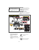
Zoom® Owner/Operator Manual Models 915107 – 2450 915105 – 2150 915103 – 1840 915101 – 1634 ENGLISH 02997700B 2/08 Printed in USA
TABLE OF CONTENTS SAFETY . . . . . . . . . . . . . . . . . . . . . . . . . 3 STORAGE . . . . . . . . . . . . . . . . . . . . . . 25 ASSEMBLY. . . . . . . . . . . . . . . . . . . . . . . 9 TROUBLESHOOTING . . . . . . . . . . . . . 25 CONTROLS AND FEATURES . . . . . . . 11 SERVICE PARTS . . . . . . . . . . . . . . . . . 28 OPERATION . . . . . . . . . . . . . . . . . . . . . 12 ACCESSORIES . . . . . . . . . . . . . . . . . . 28 MAINTENANCE SCHEDULE . . . . . . . . 15 SPECIFICATIONS . . . . . . . . . .
DELIVERY 2. Understand all Safety Precautions provided in the manuals. 3. Review control functions and operation of the unit. Do not operate the unit unless all controls function as described in this manual. 4. Review recommended lubrication, maintenance and adjustments. 5. Review Limited Warranty Policy. 6. Fill out a product registration card and return the card to the Ariens Company or go to www.ariens.com.
NOTATIONS CAUTION: POTENTIALLY HAZARDOUS SITUATION! If not avoided, MAY RESULT in minor or moderate injury. It may also be used to alert against unsafe practices. NOTE: General reference information for proper operation and maintenance practices. IMPORTANT: Specific procedures or information required to prevent damage to unit or attachment. SAFETY DECALS AND LOCATIONS ALWAYS replace missing or damaged Safety Decals. Refer to figure 2 for Safety Decal locations. 7 2 1 6 3 077541 5 8 4 Figure 2 1.
Always stand clear of discharge area. Do not direct discharge toward other people. OL1805 OL1810 Keep people away from unit while operating. Never carry children. OL1806 OL18111 Shut off engine, remove key, and read manual before you adjust or repair unit. 10 OL1812 NO STEP! Always keep feet away from rotating parts. • If machine stops going uphill, stop blade and back down slowly. • Avoid sudden turns. • Keep safety devices (guards, shields, switches, etc.) in place and working.
8. DANGER! Keep hands and feet away. Do not operate mower unless guards are in operating position or bagger is attached. EMISSION CONTROL SYSTEM CERTIFICATION LABEL Tampering with emission controls and components by unauthorized personnel may result in severe fines or penalties. Emission controls and components can only be adjusted by EPA and/or CARB authorized service centers. Contact your Ariens Equipment Retailer concerning emission controls and component questions.
NEVER direct discharge towards persons or property. Thrown objects may ricochet back towards operator. ALWAYS stand clear of the discharge area. ALWAYS disengage attachment, stop unit and engine, remove key, engage parking brake, and allow moving parts to stop before leaving operator’s position. Use extreme caution on gravel surfaces. Disengage PTO when attachment is not in use and when crossing gravel surfaces. DO NOT operate unit if safety interlock system is damaged or disabled.
NEVER fill containers inside a vehicle or on a truck or trailer bed with a plastic liner. Always place containers on the ground away from your vehicle before filling. When practical, remove gas-powered equipment from the truck or trailer and refuel it on the ground. If this is not possible, then refuel such equipment on a trailer with a portable container, rather than from a gasoline dispenser nozzle.
ASSEMBLY Check Tire Pressure WARNING: AVOID INJURY. Read and understand the entire Safety section before proceeding. CAUTION: Avoid injury! Explosive separation of tire and rim parts is possible when they are serviced incorrectly: • Do not attempt to mount a tire without the proper equipment and experience to perform the job. • Do not inflate the tires above the recommended pressure. • Do not weld or heat a wheel and tire assembly. Heat can cause an increase in air pressure resulting in an explosion.
Check function of all controls See OPERATION on page 12. 1 2 3 1 1. Steering Lever 2. Seat 3.
CONTROLS AND FEATURES 2 1 3 4 5 6 7 7 8 11 915107 3 10 1 9 4 915105, 103, 101 Figure 4 1. Throttle Lever 2. Choke Control 3. Ignition Switch 4. PTO Switch 5. Seat 6. Steering Levers 7. Fuel Tank 8. Mower Lift Pedal 9. Mower Deck 10. Discharge Chute 11.
OPERATION WARNING: AVOID INJURY. Read and understand the entire Safety section before proceeding. Safety Interlock System WARNING: Safety interlock failure and improper operation of unit can result in death or serious injury. Check system before each use to make sure it is functioning properly. CONTROLS AND FEATURES See figure 4 for all controls and features locations. Perform the following tests to ensure the safety interlock system is working properly.
Power Take-Off (PTO) Switch 1 Engages (2) and disengages (1) mower blades. 3 2 1 2 Steering Levers • • • • Reverse (1) – Pull both steering levers backward. Forward (2) – Push both steering levers forward. Left (3) – Pull left steering lever back or push right steering lever forward or a combination of both. Right (4) – Pull right steering lever back or push left steering lever forward or a combination of both. 2 1 1. Mower Lift Pedal 2. Adjustment Hole 3.
STARTING AND SHUTTING OFF ENGINE FOR BEST PERFORMANCE Starting the Engine NOTE: Disengage the PTO, engage the parking brake, and place the steering levers in neutral prior to starting the engine. 1. If the engine is cold, move the choke control to the On position. If the engine is warm or hot, do not use choke. 2. Move the throttle to 1/3 Fast position. See Engine Manual for detailed instructions. IMPORTANT: DO NOT operate starter for more than 15 seconds per minute as damage can occur. 3.
MAINTENANCE SCHEDULE WARNING: AVOID INJURY. Read and understand the entire Safety section before proceeding. Interval Task Each Use Check Safety Interlock System IMPORTANT: Proper maintenance can prolong the life of unit. The following chart shows the recommended service schedule. Refer to the maintenance instructions in the Engine Manual for additional information.
Interval Task Action Each Use Follow Engine Manual Maintenance Schedule Perform scheduled engine maintenance. Refer to Engine Manual for detailed instructions. NOTE: To drain the oil, use the oil drain petcock (1) supplied with unit, not the drain plug that is shown in the Engine Manual. Check Battery Lubricate Unit Keep battery and battery terminals clean (see Cleaning Battery and Battery Cables on page 21).
SERVICE AND ADJUSTMENTS WARNING: AVOID INJURY. Read and understand the entire Safety section before proceeding. TIPPING SEAT FORWARD Put steering levers up and tip seat forward (figure 7). MOWER DECK REMOVAL AND INSTALLATION Remove (Figure 8) 1. Remove PTO belt from electric clutch (see REPLACING PTO BELT on page 23). NOTE: Perform step 2 and 3 for the right and left side of unit. 2. Remove drag link from mower deck. 3. Remove front and rear trunnions from lift arms. 4.
Install (Figure 8) 3. Install drag link on mower deck. 4. Install PTO belt on electric clutch (see REPLACING PTO BELT on page 23). 5. Level and adjust pitch of mower deck (see LEVELLING AND ADJUSTING PITCH OF MOWER DECK on page 18). 1. Slide mower deck under unit. NOTE: Perform step 2 and 3 for the right and left side of unit. 2. Install front and rear trunnions on lift arms. 6 1 4 3 2 1. Rear Trunnion 2. PTO Belt 3. Mower Deck 6 5 4. Drag Link 5. Front Trunnion 6.
The Forward Pitch Of The Mower Blades (Figure 10): Lowest Cutting Position 3 1 2 • Should be 0.0 in. (0.0 mm) to 1/4 in. (6.35 mm) pitched forward. NOTE: This measurement must be taken when the mower blades ends are facing forward. Forward Pitch of Mower Blades 3 1 2 1-1/2 in. + 1/4 in. (3.8 cm + 0.64 cm) Highest Cutting Position 3 1 2 Forward Pitch = 0.0 in. (0.0 mm) to 1/4 in. (6.35 mm) Front of Mower Deck 1. Mower Deck 2. Mower Blade 4-1/2 in. + 1/4 in. (11.4 cm + 0.64 cm) 1. Mower Deck 2.
Adjusting The Mower Deck To Adjust Mower Blade Height And Pitch (Figure 12): NOTE: Adjusting the mower deck will adjust he height and pitch of the mower blades. 1. Adjust the trunnions first and re-take the three measurements required to level and adjust the pitch of the mower deck. These measurements are: a. The distance from the mower blades to the ground. b. The forward pitch of the mower blades. REPLACING MOWER BLADE Remove (Figure 13) CAUTION: Mower blades are sharp and can cut you.
1. Remove mower blade from unit (see REPLACING MOWER BLADE on page 20). Ariens recommends having mower blades sharpened by a professional. Contact your Ariens dealer. Discard mower blade if (figure 13): • more than 1/2 in. (1.27 cm) of metal is removed. • the air lift erosion area is eroded. • the mower blade is bent or broken. Do not change angle of cutting edge or round the corner at the end of mower blade. 2. Sharpen mower blade by removing an equal amount of material from each end of mower blade. 3.
3. Clean battery cable ends, negative (–) terminal, and positive (+) terminal with a wire brush and rinse with a weak baking soda solution. 4. Connect positive (+) cable first, then negative (–) cable. 5. Apply petroleum jelly or dielectric grease to battery cable ends and terminals. 6. Tip seat back (see TIPPING SEAT FORWARD on page 17).
REPLACING PTO BELT Forward and Reverse Speed Adjustment Remove (Figure 15) (Figure 14) 1. Lower mower deck to the ground. 2. Remove belt covers from mower deck. IMPORTANT: The unit should track within 2 feet (0.61 m) of a straight line for 30 feet (9.14 m). The travel of the steering levers may need adjustment if: • The unit turns to the right or left when both steering levers are pushed as far forward as possible.
REPLACING HYDROSTATIC BELT Install (Figure 16) 1. Install hydrostatic belt on idler, electric clutch, pulley, and hydrostatic transmission pulleys. 2. Connect idler spring. 3. Connect electric clutch connector. 4. Install PTO belt (see REPLACING PTO BELT on page 23). Remove (Figure 16) 1. Remove PTO belt (see REPLACING PTO BELT on page 23). 2. Disconnect Electric Clutch Connector from PTO. CAUTION: Use care when releasing idler spring tension.
STORAGE Short Term Storage Fuel System IMPORTANT: NEVER clean unit with highpressure water or store unit outdoors. Remove all dirt, grease, leaves, etc. Store in a clean dry area. Inspect unit for signs of wear or damage. Ensure all fasteners are properly tightened. Gasoline left in the fuel system for extended periods without a stabilizer will deteriorate, resulting in gum deposits in the system. These deposits can damage the carburetor and the fuel hoses, filter and tank.
PROBLEM Engine runs rough. Unit does not move with engine running when using steering levers. PTO or mower blades do not engage or shuts off. Engine overheats. Unit moves with engine off and parking brake engaged. PROBABLE CAUSE CORRECTION 1. Choke engaged. 1. Disengage choke. 2. Air filter cartridge plugged. 2. Clean or replace air filter cartridge. Refer to Engine Manual for detailed instructions. 3. Faulty engine. 3. Contact your Ariens Dealer. 1. The transmission bypass lever is engaged.
PROBLEM Unit does not travel in a straight line. PROBABLE CAUSE CORRECTION 1. Incorrect tire pressure. 1. Check tire pressure (see SPECIFICATIONS on page 29) 2. Steering levers need adjustment. 2. Adjust steering levers (see Forward and Reverse Speed Adjustment on page 23) 3. Hydrostatic transmission and/or linkage needs adjustment. 3. Contact your Ariens Dealer. Unit creeps with steering levers in neutral position. 1. Hydrostatic transmission and/or linkage needs adjustment. 1.
SERVICE PARTS ACCESSORIES Be sure to always use genuine Ariens parts to keep your unit running like new. See your authorized Ariens dealer to add these optional accessories to your unit. Part No. Description Part no.
SPECIFICATIONS Model Number Model Engine Type Engine Power – hp (kW) at Maximum RPM Governed RPM (May be different from maximum RPM) Speed Forward Max. – m.p.h (km/h) Reverse Max. – m.p.h (km/h) Turning Radius Brakes Electrical Starter Battery PTO (Power TakeOff) Fuel Fuel Type Fuel Tank Capacity – gal. (L) Transmission Size and Weight Length – in. (cm) Width – in. (cm) Weight – lbs (kg) Height – in. (cm) Tires Front Tire Size – in. (cm) Rear Tire Size – in.
Two-Year Limited Lawn and Garden Consumer Ride-On Warranty Ariens Company (Ariens) warrants to the original purchaser that Ariens and Gravely brand consumer products manufactured and sold by Ariens after December 31, 2007 will be free from defects in material and workmanship for a period of two years after the date of purchase.
Exceptions and Limitations • Batteries are warranted only for a period of 12 months after date of purchase, on a prorated basis. For the first 90 days of the warranty period, a defective battery will be replaced free of charge. If the applicable warranty period is more than 90 days, Ariens will cover the prorated cost of any defective battery, for up to 12 months after the date of purchase.
Ariens Company 655 West Ryan Street Brillion, WI 54110-1072 920-756-2141 Fax 920-756-2407 www.ariens.