Zoom® Owner/Operator Manual Manuel du Propriétaire/Utilisateur Models 915157 – Zoom 34 (SN 030000 +) 915159 – Zoom 42 (SN 030000 +) 915161 – Zoom 50 (SN 030000 +) 915169 – Zoom 34 CARB (SN 030000 +) 915171 – Zoom 42 CARB (SN 030000 +) E10 The use of any gasoline exceeding 10% ethanol (E10) or 10% MTBE will void the product warranty. L’utilisation d’une essence contenant plus de 10% d’éthanol (E10) ou de 10% de MTBE annulent la garantie.
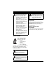
TABLE OF CONTENTS SAFETY. . . . . . . . . . . . . . . . . . . . . . . . . . 4 STORAGE . . . . . . . . . . . . . . . . . . . . . . . 31 ASSEMBLY . . . . . . . . . . . . . . . . . . . . . . 11 TROUBLESHOOTING . . . . . . . . . . . . . 32 CONTROLS AND FEATURES . . . . . . . 13 SERVICE PARTS . . . . . . . . . . . . . . . . . 33 OPERATION . . . . . . . . . . . . . . . . . . . . . 14 ACCESSORIES. . . . . . . . . . . . . . . . . . . 33 MAINTENANCE SCHEDULE . . . . . . . . 20 SPECIFICATIONS . . . . . . . .
Customer Note: If the dealer does not register your product, please fill out, sign and return the product registration card to Ariens or go to www.ariens.com on the Internet. UNAUTHORIZED REPLACEMENT PARTS Use only Ariens replacement parts. The replacement of any part on this unit with anything other than an Ariens authorized replacement part may adversely affect the performance, durability, and safety of this unit and may void the warranty.
SAFETY WARNING: This cutting machine is capable of amputating hands and feet and throwing objects. Failure to observe the safety instructions in the manuals and on decals could result in serious injury or death. Slopes are a major factor related to loss-of-control and tip-over accidents. Operation on all slopes requires extra caution. Tragic accidents can occur if the operator is not alert to the presence of children. Never assume that children will remain where you last saw them.
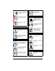
7 4 07800401 6 2 5 KEEP HANDS and FEET AWAY 02 98 81 00 3 1 2 P 07800403 Figure 2 1. DANGER! 2. DANGER! Discharge Hazard NEVER operate unit without discharge chute in operating position. Thrown objects can cause injury or damage. Discharge Hazard NEVER direct discharge toward people, pets or property. Thrown objects can cause injury or damage. Do not operate mower unless all guards are in operating position or bagger is attached.
Keep children and others away from unit while unit is in operation. Keep all guards and shields in place. 3.2 Discharge Hazard Keep feet and hands away from all rotating or moving parts. Discharge Hazard NEVER direct discharge toward people, pets or property. Thrown objects can cause injury or damage. DO NOT step or stand in this area. Keep children and others away from unit while unit is in operation. 3. DANGER! Do not operate mower unless all guards are in operating position or bagger is attached.
Read owners manual before servicing or making adjustments to unit. Proceed off slope slowly. P Do not try to turn or speed up. Set parking brake. Remove key and disconnect spark plug before servicing or making adjustments to unit. 4. DANGER! To avoid dismemberment hazard do not put hands near moving belts. 3.5 Bystander Hazard DO NOT operate the unit in the presence of bystanders. Keep hands away from all rotating or moving parts. Do not carry passengers. 5.
6. DANGER! DO NOT touch parts which are hot from operation. ALWAYS allow parts to cool. 7. CAUTION! No smoking. IMPORTANT: DO NOT overfill. Fill fuel tank to below bottom of filler neck. WARNING: Overfilling may cause severe damage to evaporative system! • • Never fill fuel tank when engine is running, hot or unit is indoors. Never overfill fuel tank. Replace fuel cap securely and clean up spilled fuel.
Protect eyes, face and head from objects that may be thrown from unit. Wear appropriate hearing protection. Always wear safety goggles or safety glasses with side shields when operating mower. Avoid sharp edges. Sharp edges can cut. Moving parts can cut off fingers or a hand. ALWAYS keep hands and feet away from all rotating parts during operation. Rotating parts can cut off body parts. ALWAYS keep hands away from all pinch points. Start and operate unit only when seated in operator’s position.
Do not use hitch with bagger attached. Do not use on steep hills or slopes. Do not park on hills when trailer is attached. Do not use with any ground engaging equipment. NEVER allow children or others in or on towed equipment. On slopes, the weight of the towed equipment may cause loss of traction and loss of control. Travel slowly and allow extra distance to stop. Use extra care when loading or unloading unit onto trailer or truck. Secure unit chassis to transport vehicle.
Stop and inspect equipment if you strike an object or if there is an unusual vibration. Repair, if necessary, before restarting. Never make adjustments or repairs with the engine running. Mower blades are sharp and can cut you. Wrap the blade(s) or wear gloves, and use extra caution when servicing them. NEVER weld or straighten mower blades. Rotation of one blade may cause rotation of the other blades. Check brake operation frequently. Adjust and service as required. Keep all hardware properly tightened.
Check Tire Pressure CAUTION: Avoid injury! Explosive separation of tire and rim parts is possible when they are serviced incorrectly: • Do not attempt to mount a tire without the proper equipment and experience to perform the job. • Do not inflate the tires above the recommended pressure. • Do not weld or heat a wheel and tire assembly. Heat can cause an increase in air pressure resulting in an explosion. Welding can structurally weaken or deform the wheel.
CONTROLS AND FEATURES 5 3 6 12 4 14 10 9 915159, 161, 171 13 7 8 2 915157, 169 11 1 2 1 11 Figure 4 1. Ignition Switch 2. PTO Switch 3. Seat 4. Fuel Level 5. Steering Levers 6. Fuel Tank 7. Mower Lift Pedal 8. Mower Deck 9. Discharge Chute 10. Parking Brake Lever 11. Throttle/Choke Lever 12. Seat Adjustment Lever (915159, 161, 171) 13. Height of Cut Selector Lever 14.
OPERATION Safety Interlock System WARNING: AVOID INJURY. Read and understand the entire Safety section before proceeding. WARNING: Safety interlock failure and improper operation of unit can result in death or serious injury. Check system before each use to make sure it is functioning properly. CONTROLS AND FEATURES See Figure 4 for all controls and features locations. Perform the following tests to ensure the safety interlock system is working properly.
Throttle/Choke Lever (915157, 169) Choke (1) – Use to start a cold engine. Push throttle lever past detent for choke to start a cold engine. Pull throttle lever back past detent to close choke for a warm engine. Fast (2) – Increases engine speed. 1 2 Slow (3) – Decreases engine speed. 3 Parking Brake Lever 1 Engages (2) and disengages (1) parking brake. 2 3 4 NOTE: To stop, return both steering levers to neutral. NOTE: The steering levers must be in the neutral position to start the engine.
1 3 4 2 5 Figure 6 1. 2. 3. 4. 5. Seat Adjustment (915157, 169) 1. Tip the seat forward. See “TIPPING SEAT FORWARD” on page 22. 2. Loosen mounting hardware and slide seat forward or backward to desired position. Tighten mounting hardware (figure 9). 3. Tip seat back. Deck Port Hose Coupling Lock Collar Mower Deck Standard Garden Hose Figure 7 1. Park the unit on a level surface, within reach of hose and in a location where the dispersal of wet grass clippings is acceptable. 2.
NOTE: If water leaks excessively from hose coupling onto top of deck, coupling may not be fully seated onto washout port. Turn off water supply and repeat steps 4 through 6. Use firm pressure while installing coupling onto washout port. WARNING: When using the deck wash system, NEVER engage the deck from any position other than the operator’s seat. DO NOT engage deck in the presence of ANY bystander. 7. From the operators seat, start the engine and engage the PTO.
Fuel Stabilizer Gasoline left in the fuel system for extended periods without a stabilizer will deteriorate, resulting in gum deposits in the system. These deposits can damage the carburetor and the fuel hoses, filter and tank. Prevent deposits from forming in the fuel system during storage by adding a quality fuel stabilizer to the fuel. Follow the recommended mix ratio found on the fuel stabilizer container. 5. Wait until the engine is running smoothly before operation.
MOVING UNIT MANUALLY (Figure 8) WARNING: DO NOT disengage or bypass transmission and coast downhill. Pull the bypass lever out and lock it in place, and then release the parking brake to push the unit by hand. Push the bypass lever in to drive the unit normally. NOTE: There are two bypass levers; one on each side of the unit. 1 2 1. Bypass lever pulled out to push the unit by hand. 2. Bypass lever pushed in to drive the unit.
MAINTENANCE SCHEDULE WARNING: AVOID INJURY. Read and understand the entire Safety section before proceeding. NOTE: To have full access to the engine, the seat must be tipped forward "TIPPING SEAT FORWARD" on page 22 and the hood opened "OPENING AND CLOSING HOOD" on page 22. IMPORTANT: Proper maintenance can prolong the life of unit. The following chart shows the recommended service schedule. Refer to the maintenance instructions in the Engine Manual for additional information.
Interval Task Action Each Use Follow Engine Manual Maintenance Schedule Perform scheduled engine maintenance. Refer to Engine Manual for detailed instructions. NOTE: To drain the oil, remove oil drain cap and attach the oil drain hose, supplied in the lit pack, to the drain plug. Rotate the drain to the left to allow oil to drain. Turn the drain to the right to close. Oil Drain Plug 25 Hours or Every Season Check Battery Lubricate Unit Keep battery and battery terminals clean.
SERVICE AND ADJUSTMENTS MOWER DECK REMOVAL AND INSTALLATION WARNING: AVOID INJURY. Read and understand the entire Safety section before proceeding. Remove TIPPING SEAT FORWARD (Figure 9) Move steering levers to neutral position and rotate handles outward. Tip seat forward. 3 (Figure 11) 1. Remove PTO belt from the engine drive pulley. See “REPLACING PTO BELT” on page 29. 2. Disconnect drag link from the front deck bracket. 3.
7 1 1. 2. 3. 4. 5. 6. 7. Rear Trunnion PTO Belt Mower Deck Drag Link Front Trunnion Lift Arms Nuts 6 2 3 5 7 6 Figure 11 LEVELING AND ADJUSTING PITCH OF MOWER DECK NOTE: Adjust on a level surface, with the tires inflated to the correct air pressure. See “SPECIFICATIONS” on page 34. Three measurements are required to level and adjust the pitch of the mower deck. 1. The distance from the mower blades to the ground. 2. The forward pitch of the mower blades. 3.
The Forward Pitch Of The Mower Blades Adjusting The Mower Deck To Adjust Mower Blade Height And Pitch (Figure 13) • Should be 0" (0 cm) to 1/4" (0.635 cm) pitched forward. NOTE: This measurement must be taken when the mower blades ends point forward. (Figure 15) NOTE: Adjusting the mower deck will adjust the height and pitch of the mower blades. 1. Adjust the trunnions first and re-take the three measurements required to level and adjust the pitch of the mower deck. These measurements are: a.
REPLACING MOWER BLADE Remove (Figure 16) CAUTION: Mower blades are sharp and can cut you. Wrap the blades or wear gloves, and use extra caution when servicing them. 1. Block mower blades to prevent rotation. 2. Remove mounting hardware and mower blades from spindles. Install (Figure 16) 1. Install mower blades on spindles with mounting hardware. 2. Torque 5/8" nut to 100 to 120 lbf-ft (136 to 163 N•m). 1 2 1. Remove mower blade from unit. See “REPLACING MOWER BLADE” on page 25.
SERVICING THE BATTERY 4. Remove nut and bolt securing battery hold down bracket. Save for reinstallation. NOTE: The bolt securing the battery is mounted through the underside of the frame. Place hand beneath frame to catch loose bolt. 5. Remove battery from unit. NOTE: Unit comes equipped with a maintenance-free battery that requires no regular maintenance except cleaning the terminals.
U1 Battery Installation Cleaning Battery and Battery Cables (Figures 19 and 20) 1. Remove factory battery. See “Remove Factory-Installed Battery” on page 26. NOTE: Be sure to cut cable tie connecting positive battery cable to battery hold down bracket. 2. Set battery inside the frame, underneath the seat with terminals positioned as shown (Figure 20). 3. Place battery hold down bracket on top of the battery.
ADJUSTING STEERING LEVERS 4. Charge battery according to battery charger and battery manufacturers’ instructions. 5. Install battery on unit. See “FactoryInstalled Battery Removal and Installation” on page 26. (Figure 22) Adjustment 3 Jump-Starting 1 Ariens does not recommend jump-starting your unit. Jump-starting can damage engine and electrical system components. See your engine manual for more detailed information.
Rotate this end away from the operator position to move the steering levers in. 2 Rotate this end away from the operator position to move the steering levers out. 1 Figure 23 1. Forward Travel Adjustment Bolt 2. Lower Control Arm 3. Adjust Steering Lever Forward or Backward 1. Loosen, do not remove, the bolts securing the handlebar to the upper control arm. 2. Rotate steering lever forward or backward to desired position and tighten bolts. NOTE: Tighten upper bolt first.
915157, 169 3 Install 1 (Figure 25) NOTE: Do not install PTO belt on left mower deck pulley in step 1. 1. Install PTO belt on engine drive pulley and mower deck. 2. Rotate idler arm clockwise until PTO belt can be routed around left mower deck pulley. 3. Slowly release idler arm until idler pulley rests firmly against PTO belt. 4. Install belt covers on mower deck. NOTE: Ensure that belt is still positioned in the groove of the sheaves after belt covers are installed. 1 4 2 1. 2. 3. 4.
1 4 IMPORTANT: NEVER store the engine with fuel in the fuel tank inside of a building with potential sources of ignition. 2 2 Add Fuel Stabilizer 1. Drain fuel from fuel tank. 2. Allow the engine to run until it stops. Turn engine OFF when it begins surging to avoid engine damage. 3. Add fuel stabilizer to fuel, following the manufacturer’s instructions. 4. Pour fuel into the tank. 5. Re-start engine. 6.
TROUBLESHOOTING PROBLEM Engine will not crank/start. Engine runs rough. Unit does not move with engine running when using steering levers. PTO or mower blades do not engage or shut off. Engine overheats. PROBABLE CAUSE CORRECTION 1. Safety interlock system is not engaged or is faulty. 1. Check safety interlock system. See “Safety Interlock System” on page 14. 2. Fuel tank is empty. 2. Fill fuel tank. See “FILLING FUEL TANK” on page 17. 3. Discharged battery. 3. Charge battery.
PROBLEM PROBABLE CAUSE CORRECTION Unit moves with engine off and parking brake engaged. 1. The parking brake needs adjustment. 1. Contact your Ariens dealer. 2. Faulty parking brake. 2. Contact your Ariens dealer. Unit does not travel in a straight line. 1. Incorrect tire pressure. 1. Check tire pressure. See “SPECIFICATIONS” on page 34. 2. Steering levers need adjustment. 2. Adjust steering levers. See “Forward Speed Adjustment” on page 29. 3.
SPECIFICATIONS Model Number Model 915157 915159 915161 Zoom 34 Zoom 42 Zoom50 Engine Briggs & Stratton Type Engine Displacement in.3 (cc) Kohler 30.51 (500) Governed RPM (May be different from maximum RPM) 44.2 ( 725) 3600 + 0 3600 – 100 Drive Forward Max. – m.p.h (km/h) 6.0 (9.6) Reverse Max. – m.p.h (km/h) 3.0 (4.
SPECIFICATIONS Model Number Model 915169 915171 Zoom 34 CARB Zoom 42 CARB Briggs & Stratton Kohler 30.51 (500) 44.2 (725) Engine Type Engine Displacement in.3 (cc) Governed RPM (May be different from maximum RPM) 3600 + 0 3600 – 100 Drive Forward Max. – m.p.h (km/h) 6.0 (9.6) Reverse Max. – m.p.h (km/h) 3.0 (4.
Consumer Mowing Equipment Limited Warranty Ariens Company (Ariens) warrants to the original purchaser that Ariens, Gravely and Countax brand lawn and garden consumer products purchased on or after 1/1/2013 will be free from defects in material and workmanship for the time period noted in the chart below.
• Transport the product to and from the place of warranty service at owner's expense. • Have the warranty service performed by an authorized Ariens, Gravely or Countax service representative. To Find an Authorized Service Representative: In the U.S. and Canada: Use the dealer locator on our websites: www.ariens.com • www.gravely.com Or contact us by mail or by phone: In the U.S., Canada, Mexico, Caribbean, In Europe, Asia, Africa or Central and South America: the Middle East: Ariens Company 655 W.
Ariens 655 West Ryan Street Brillion, WI 54110 920-756-4688 Fax 920-756-2407 www.ariens.com www.ariens.com.