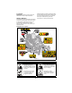
IKON-X IKON-XL Operator’s Manual Manuel du Utilisateur Models 915220 – IKON-X 42 (SN 000101 +) 915222 – IKON-X 52 (SN 000101 +) 915223 – IKON-X 52 (SN 000101 +) 915224 – IKON-X 42 CARB (SN 000101 +) 915225 – IKON-X 52 CARB (SN 000101 +) 915226 – IKON-XL 42 (SN 000101 +) 915227 – IKON-XL 52 (SN 000101 +) 915228 – IKON-XL 60 (SN 000101 +) 915229 – IKON-XL 60 (SN 000101 +) E10 ENGLISH FRANÇAIS 05101800 • 10/16 Printed in USA ™ ™
TABLE OF CONTENTS WELCOME . . . . . . . . . . . . . . . . . . . . . . 1 SAFETY. . . . . . . . . . . . . . . . . . . . . . . . . 2 Practices & Laws . . . . . . . . . . . . . . . . . . Emission Control System. . . . . . . . . . . . Required Operator Training . . . . . . . . . . Safety Alert Symbol . . . . . . . . . . . . . . . . Signal Words . . . . . . . . . . . . . . . . . . . . . Safety Decals. . . . . . . . . . . . . . . . . . . . . Safety Rules. . . . . . . . . . . . . . . . . . . . . .
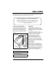
WELCOME Congratulations on your purchase and welcome to the Ariens family! Every machine in the Ariens lineup is designed for long-lasting and unsurpassed performance. We are confident your machine will be part of your family for many years to come. Have Questions or Need Assistance? ariens.custhelp.com • ariensstore.com A parts manual for your unit is available for free download or purchase at ariens.com.
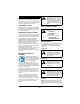
SAFETY WARNING: AVOID INJURY. This cutting machine is capable of amputating hands and feet and throwing objects. Failure to observe the safety instructions in the manuals and on decals could result in serious injury or death. Read these safety rules and follow them closely. Failure to follow these rules could lead to loss of control of unit, severe personal injury or death to you or bystanders, or result in damage to property or the machine.
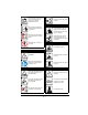
. Important ALWAYS replace missing or damaged safety decals. Replacement decal part numbers are found in the parts manual for your machine and may be ordered from your dealer. See Figure 2 for safety decal locations. IMPORTANT: Indicates general reference information worthy of special attention. SAFETY DECALS The safety decals on your machine are visual reminders of the important safety information in this manual. All messages on your unit must be fully understood and carefully followed.
Shut off engine, remove key, and read manual before servicing or making adjustments to unit. Keep all guards and shields in place. 3.2 Discharge Hazard Keep children and others away from unit while unit is in operation. Discharge Hazard - NEVER direct discharge toward people, pets or property. Thrown objects can cause injury or damage. Keep feet and hands away from all rotating or moving parts. DO NOT operate mower unless all guards are in operating position or bagger is attached.
Remove key and disconnect spark plug before servicing or making adjustments to unit. 5. HOT PARTS! DO NOT touch parts which are hot from operation. ALWAYS allow parts to cool. 3.5 Bystander Hazard DO NOT operate the unit in the presence of bystanders. 6. ROTATING PARTS! AVOID INJURY. Stay clear of rotating parts. DO NOT carry passengers. 7. DANGER! Look behind when operating the unit in reverse. DANGER! 3.6 Loss of Traction Hazard No smoking.
Operator Age 8. CAUTION! DO NOT allow children under the age of 18 to operate any outdoor power equipment. • Maximum tongue weight: 30 lbs. • Maximum trailer weight: 300 lbs. • Do not use hitch with bagger attached. • Do not use on steep hills or slopes. • Do not park on hills when trailer is attached. • Do not use with any ground engaging equipment. Local regulations may restrict the age of the operator.
DO NOT touch parts which are hot. Allow parts to cool. Before Operating Keep all nuts and bolts tight to be sure the equipment is in safe working condition. DO NOT operate machine without the entire grass catcher, discharge guard or other safety devices in place and working. Maintain the machine to be in compliance with the maintenance schedule. Clean grass and debris from unit, especially from around muffler and engine, to help prevent fires. Check parking brake operation frequently.
Operating Conditions Lightning can cause severe injury or death. If lightning is seen or thunder is heard in the area, do not operate the machine, see shelter. ALWAYS check overhead and side clearances carefully before operation. Watch for traffic when operating near or crossing roadways. Clear the area of objects such as rocks, wire, toys, etc., which could be thrown by the blades. Check for weak spots on docks, ramps or floors. Avoid uneven work areas and rough terrain.
Fuel is highly flammable and its vapors are explosive. Handle with care. Use only an approved gasoline container with an appropriately-sized dispensing spout. NO smoking, NO sparks, NO flames. Batteries Avoid electric shock. Objects contacting both battery terminals at the same time may result in injury and unit damage. DO NOT reverse battery connections. Remove gas-powered equipment from the trailer and refuel it on the ground.
Lower cutting deck unless a positive mechanical lock is used. Allow engine to cool before servicing. Moving parts can cut or amputate fingers or a hand. On multiblade mowers, rotation of one blade will cause all blades to rotate. NEVER weld or straighten mower blades. NEVER make adjustments or repairs with the engine running. Mower blades are sharp. Wrap the blade or wear gloves, and use extra caution when servicing them.
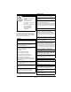
CONTROLS AND FEATURES 22 6 5 10 7 8 9 17 1 20 16 4 12 2 21 3 13 Models 915220, 915222, 915224, 915225, 915226, 915227, 915228 11 Models 915223, 915229 14 4 18 19 2 1. 2. 3. 4. 5. 6. 7. 8. 9. 10. 11. 3 Fuel Tank and Cap Oil Filter Oil Drain Engine Oil Dipstick Ignition Key Choke Control Knob Throttle Control Lever Power Take-off (PTO) Knob Hour Meter Height-of-Cut Dial Deck Lift Pedal Figure 3 12. 13. 14. 15. 16. 17. 18. 19. 20. 21. 22.
THROTTLE CONTROL LEVER WARNING: AVOID INJURY. Read and understand the entire Safety section before proceeding. See Figure 6. Controls engine speed. See Figure 3 for all controls and features locations. Fast IGNITION KEY See Figure 4. Controls power to the engine. The key cannot be removed when in run position. On With Headlights (If Equipped) Slow On Figure 6 Start Off POWER-TAKE-OFF (PTO) KNOB See Figure 7. Controls power to mower blades.
PARKING BRAKE LEVER OPERATION See Figure 8. Controls the parking brake. The engine will not start with brake in the off position. WARNING: AVOID INJURY. Read and understand the Safety section before proceeding. Parking Brake Engaged (On) IMPORTANT: All references to left, right, front or rear are given from the perspective of operator in operator’s position, facing the direction of forward travel. EMERGENCY STOPPING 1. 2. 3. 4. Brake Released (Off) Move steering levers to neutral position.
5. Set cutting height. See Figure 9. a. Depress and hold deck lift pedal in forward position. b. Rotate height-of-cut dial to desired setting. c. Slowly return deck lift pedal to resting position. 1 OPERATE UNIT 1. Release parking brake. WARNING: AVOID INJURY. Move the steering levers slowly and keep the throttle at slow speed until you learn how to operate the unit. 2. Set throttle to slow speed. 3. Pull PTO knob up to on position.
For Best Mowing Results • • • • • • • • • • Cut grass when it is dry. Keep mower blades sharp. Keep mower deck properly leveled. Do not set height of cut too low. For very tall grass, mow twice. Do not travel too fast. Mow with the engine set at full throttle. When mulching, only remove 1/3 of grass length per cutting. Do not cut more than 2.5 cm (1") at any one time. Discharge clippings into areas already cut. Vary cutting pattern with each mowing.
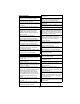
TRANSPORT UNIT SERVICE PARTS 1. Stop engine, set parking brake and remove key from ignition. 2. Secure unit chassis to transport vehicle. See your Ariens dealer to purchase service parts for your unit. Model 915220 NOTICE: NEVER secure from rods or linkages that could be damaged. Description MAINTENANCE Qty. Part No.
Description Qty. Part No. Drive Wheel and Tire Assembly 1 Seat Switch 1 Description 07101130 1 51528800 Armrest Kit – Right 1 51528900 Spark Plug AR 00057100 1 21536100 Fuel Filter 1 21548101 Oil Filter 1 21548100 Air Filter 1 21548000 Transaxle Drive Belt 21555500 Model 915226 Description Qty. Part No.
Description Description Qty. Part No. Qty. Part No. Fuel Filter 1 21545700 Spark Plug 1 21536100 Oil Filter 1 21397200 Fuel Filter 1 21548101 Air Filter 1 21555500 Oil Filter 1 21548100 Air Filter 1 21548000 Model 915228 Description Transaxle Drive Belt SERVICE POSITION Qty. Part No.
CHECK SAFETY INTERLOCK SYSTEM CHECK TIRE PRESSURE Check function of the Safety Interlock System by performing the tests below. Contact your Ariens dealer for repair if any of the tests fail. See Specifications on page 36 for recommended tire pressure. WARNING: AVOID INJURY. Explosive separation of tire and rim parts is possible. • DO NOT inflate tires above the recommended pressure. • DO NOT inflate tires with a compressor; use a hand pump. • DO NOT stand in front of tire assembly when inflating.
LUBRICATE UNIT See Figure 14. 1. Place unit in service position. See Service Position on page 18. 2. Apply grease to seat tracks through slots under seat plate. 1 2 3 4 1. 2. 3. 4. Spindle Mower Blade Washer Nut Figure 15 Figure 14 Sharpen Blades 3. Return seat to operating position and slide seat back and forth to spread grease along tracks. CAUTION: DO NOT sharpen blades while attached to unit. CHECK MOWER BLADES Check blades for wear. Replace or sharpen as needed. CAUTION: AVOID INJURY.
Remove Battery DO NOT sharpen to this pattern. 1 1. Place unit in service position. See Service Position on page 18. 2. Disconnect the negative cable and then the positive cable from the battery. See Figure 17. 3. Remove hardware retaining battery brackets and remove brackets. 2 Sharpen to this pattern. IMPORTANT: Remove flange nuts and brackets only. DO NOT remove bolts from battery tray. 1 4. Remove battery. 3 2 3 1. 2. 3. 4.
Figure 18 See Figure 19. 2. Place battery on battery tray so terminals are positioned nearest right side of unit. 3. Install battery bracket over battery and onto bolts in battery tray. 4. Reinstall L-bracket onto bolt and secure with flange nut. 5. Secure remaining battery bracket end to battery tray with original flange nut. 6. Connect positive cable to positive battery terminal and then the negative cable to negative battery terminal. 7. Return seat to operating position. Figure 20 3.
4. Reinstall battery. See Install Battery on page 21. Charge Battery Check battery with a voltmeter. If battery is less than 11 volts, charge battery. NOTICE: DO NOT fast charge. Charging at a higher rate damages or destroys the battery. ONLY use an automatic charger designed for use with your battery. 2 1 IMPORTANT: Always follow information provided on battery by battery manufacturer. Contact battery manufacturer for detailed information about charging.
Install Deck Drive Belt Remove Ground Drive Belt 1. Install deck drive belt. See Figure 24. IMPORTANT: Retain all parts for reinstallation. IMPORTANT: Belt will not have tension until routed around drive pulley and idler arm is reinstalled. 1. Place unit in service position. See Service Position on page 18. 2. Remove deck drive belt. See Remove Deck Drive Belt on page 23. 3. Position deck at lowest cutting height. 4. Loosen nut on eye bolt and disconnect idler arm spring. See Figure 26.
5. Reconnect idler arm spring to eye bolt and secure bolt to unit with nut. Tighten until the nut is 6.1 cm (2.4") from the threaded end of the eye bolt. See Figure 26. 6. Reinstall deck drive belt. See Install Deck Drive Belt on page 24. 2 HYDRAULIC OIL Models 915226, 915227, 915228, 915229 Check Hydraulic Oil Level 3 See Figure 29. 1. Place unit in service position. See Service Position on page 18. 2. Check oil level in expansion tanks. Oil should reach the cold fill indicator mark. 1 1.
The hydraulic fluid should be at the cold fill line of the expansion tank. 1 2 1 1. Vent Plug 2. Oil Filter 3. Filter Guard 3 Figure 30 1. Cold Fill Indicator Mark Figure 29 Change Hydraulic Oil and Filter Models 915226, 915227, 915228, 915229 NOTICE: Change hydraulic fluid and filter after the first 75 hours of operation and then every 400 hours. Use 15W-50 synthetic motor oil (Ariens p/n 00057100) or equivalent. 1. Operate unit for a few minutes to warm hydraulic oil. 2.
Purge Hydraulic System WARNING: This adjustment requires operating the engine. Use extreme care to avoid contact with moving parts and hot surfaces. Be sure rear of unit is well supported and secure before starting engine. 1. With the unit up to and facing a wall, jack up the unit so that both drive wheels are off the ground. 2. Disengage the parking brake and put the transaxle bypass levers in the neutral position (see Move Unit Manually on page 15). 3.
Adjust Steering Lever Reach See Figure 34. 1. Loosen hardware securing steering lever to upper control arm. 2. Pivot steering lever to desired position. Ensure levers are aligned with each other. 3. Tighten hardware. 3 2 4 1 1. 2. 3. 4. 1 Adjusting Hole Mounting Hole Steering Lever Upper Control Arm Figure 32 2 See Figure 33. 6. Loosen nut on hex bolt supporting eccentric spacer. 7. Rotate eccentric spacer around hex bolt until levers are at the same height. 8. Tighten nut. 3 3 1.
Adjust Steering Levers 2 See Figure 35. If adjusting tire pressure did not correct tracking problem: 1. Loosen jam nut on adjustment bolt of steering lever that needs adjustment. 2. Adjust drive wheel speed. • Turn adjustment bolt counterclockwise to increase steering lever travel and drive wheel speed. • Turn adjustment bolt clockwise to decrease steering lever travel and drive wheel speed. 3. Tighten jam nut. IMPORTANT: Adjustment bolt must contact steering lever.
5. Remove deck drive belt from rear drive pulley. See Figure 38. 8. Remove one flange nut, one hex bolt, one flat steel washer and two sleeve bushings from deck lift lever. Retain hardware. See Figure 40. 2 5 1 3 Figure 38 4 See Figure 39. 6. Remove one hairpin from drag link to disconnect drag link from mower deck bracket. Retain all parts for reinstallation. 7. Repeat step 6 on other side. 1. 2. 3. 4. 5. Deck Lift Lever Flange Nut Hex Bolt Flat Steel Washer Sleeve Bushings 2 Figure 40 9.
7 2 3 1. Set deck to highest cutting height. 2. Position mower blades so blade ends point left to right across the width of the deck. 3. On both sides of the unit, measure the distance to the ground at the cutting edge of the blade. See Figure 42. 6 4 5 1 1. 2. 3. 4. Deck Lift Lever Deck Link 3/8 x 1/2 x 1" (Longer) Sleeve Bushing 1/2 x 3/4 x 3/64" (Shorter) Sleeve Bushing 5. Hex Bolt 6. Flat Steel Washer 7. Flange Nut Figure 42 • If the measurements are ± 0.
Set Blade Pitch Pitch is the difference in blade height from front to back. IMPORTANT: Level the mower deck before setting blade pitch. 1. Set deck to highest cutting height. 2. Position mower blades so blade ends point front to back. 3. On both sides of the unit, measure the distance to the ground at the front and rear tip of the blade. See Figure 44. Figure 44 • If the front tip of the blade is ± 0.635 cm (1/4") lower than the rear, no adjustment is needed.
TROUBLESHOOTING Problem Engine does not start. Probable Cause Safety Interlock System is not engaged or is faulty. Correction Check Safety Interlock System. See Check Safety Interlock System on page 19. Fuel tank is empty. Fill fuel tank. See Before Operating Unit on page 13. Fuel supply is contaminated. Replace with clean fuel. Battery is discharged. Charge battery. See Charge Battery on page 23. Connection between battery and Tighten and/or clean battery and battery battery cables is poor. cables.
TROUBLESHOOTING Problem Poor cutting quality. Probable Cause Mower blades not level or mower deck pitch is incorrect. Mower blades are dull or faulty. Correction Level and adjust pitch of mower deck. See Adjust Mower Deck on page 31. Sharpen or replace mower blades. See Sharpen Blades on page 20. Mowing speed is too fast. Drive slower when cutting grass. Belt tension or condition is poor. Replace deck drive belt. See Check Mower Belts on page 23. Cutting height is too low.
STORAGE ACCESSORIES SHORT-TERM STORAGE See your Ariens dealer for a complete list of compatible accessories and attachments for your unit. IMPORTANT: NEVER wash unit with highpressure water or store outdoors. 1. Allow unit to cool and clean with mild soap and water. 2. Tighten all hardware to correct specifications. 3. Inspect unit for visible signs of wear or damage. Repair as needed. 4. Prepare fuel system for storage. Description Part No.
SPECIFICATIONS Model Number 915220 Model IKON X 42 Engine 915222 915224 IKON X 52 IKON X 42 CARB Kohler 7000 Series 3 3 725.0 (44.2) Engine Displacement – cm (in ) Maximum RPM – No Load 3300 ± 75 Oil Capacity Refer to Engine Manual Drive Forward Maximum – km/h (mph) 11.3 (7.0) Reverse Maximum – km/h (mph) 4.8 (3.
SPECIFICATIONS Model Number Model Engine Engine Displacement – cm3 (in3) Maximum RPM – No Load Oil Capacity Drive Forward Maximum – km/h (mph) Reverse Maximum – km/h (mph) Turning Radius Brakes Electrical Starter Battery PTO (Power Take-off) Fuel Fuel Tank Capacity – Liter (gal) Size and Weight Length – cm (in) Width – cm (in) Weight – kg (lbs) Height – cm (in) Tires Front Tire Size – in Rear Tire Size – in Recommended Front Tire Pressure – kPa (psi) Recommended Rear Tire Pressure – kPa (psi) Mower Deck Cut
SPECIFICATIONS Model Number Model 915228 915229 IKON XL 60 IKON XL 60 Engine Kohler 7000 Series Kawasaki FR Engine Displacement – cm3 (in3) Maximum RPM – No Load Oil Capacity Drive Forward Maximum – km/h (mph) Reverse Maximum – km/h (mph) Turning Radius Brakes Electrical Starter Battery PTO (Power Take-off) Fuel Fuel Tank Capacity – Liter (gal) Size and Weight Length – cm (in) Width – cm (in) Weight – kg (lbs) Height – cm (in) Tires Front Tire Size – in Rear Tire Size – in Recommended Front Tire Pre
Consumer Mowing Equipment Limited Warranty Warr Ariens Company (Ariens) warrants to the original purchaser that Ariens, Gravely and Countax brand lawn and garden consumer products purchased on or after 9/1/2016 will be free from defects in material and workmanship for the time period noted in the chart below.
• Promptly notify Ariens or an authorized Ariens, Gravely or Countax service representative of the need for warranty service. • Transport the product to and from the place of warranty service at owner's expense. • Have the warranty service performed by an authorized Ariens, Gravely or Countax service representative. To Find an Authorized Service Representative: In the U.S. and Canada: Use the dealer locator on our websites: www.ariens.com • www.gravely.com Or contact us by mail or by phone: In the U.S.
655 West Ryan Street Brillion, WI 54110 ariensstore.com ariens.custhelp.com parts.ariens.