
Engine Service Manual


Starter System
60 32 690 03 Rev. IKohlerEngines.com
SOLENOID SHIFT STARTERS
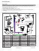
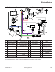
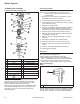
Solenoid Shift Starter Components
A
B
U
T
S
R
Q
P
O
N
M
L
K
J
I
H
G
F
E
D
C
A Tube B Washer
C Armature D Drive
E Stop F Retaining Ring
G Collar H Drive End Cap
I Screw J Plunger
K Spring L Lever
M Plate N Plug
O Solenoid P Frame and Field
Q Brush Holder R Nut
S
Commutator End
Plate
T Screw
U Bolt
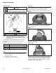
When power is applied to starter electric solenoid moves
drive pinion out onto drive shaft and into mesh with
fl ywheel ring gear. When pinion reaches end of drive
shaft it rotates fl ywheel and cranks engine.
When engine starts and start switch is released, starter
solenoid is deactivated, drive lever moves back, and
drive pinion moves out of mesh with ring gear into
retracted position.
Starter Disassembly
NOTE: Do not reuse old retainer.
NOTE: Do not soak armature or use solvent when
cleaning. Wipe clean using a soft cloth, or use
compressed air.
1. Remove hex nut and disconnect positive (+) brush
lead/bracket from solenoid terminal.
2. Remove head screws securing solenoid to starter.
3. Unhook plunger pin from drive lever. Remove gasket
from recess in housing.
4. Remove thru (larger) bolts.
5. Remove commutator end plate assembly, containing
brush holder, brushes, springs, and locking caps.
Remove thrust washer from inside commutator end.
6. Remove frame from armature and drive end cap.
7. Remove drive lever pivot bushing and backing plate
(if equipped) from end cap.
8. Take out drive lever and pull armature out of drive
end cap.
9. Remove thrust washer from armature shaft.
10. Push stop collar down to expose retaining ring.
11. Remove retainer from armature shaft. Save stop
collar.
12. Remove drive pinion assembly from armature.
13. Clean parts as required.
Inspection
Drive Pinion
Check and inspect following areas:
● Pinion teeth for abnormal wear or damage.
● Surface between pinion and clutch mechanism for
nicks or irregularities which could cause seal damage.
● Check drive clutch by holding clutch housing and
rotating pinion. Pinion should rotate in only 1 direction.
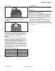
Brushes and Springs
Detail
A
A Wear Limit Length
Inspect both springs and brushes for wear, fatigue, or
damage. Measure length of each brush. Minimum length
for each brush is 7.6 mm (0.300 in.). Replace brushes if
they are worn, undersize, or condition is questionable.