
Engine Service Manual


85
Reassembly
32 690 03 Rev. I KohlerEngines.com
Adjust Valve Clearance
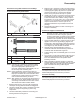
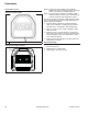
Adjusters Retaining Push Rods
A
B
A Adjuster B Rocker Arm
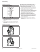
1. Rotate crankshaft to establish TDC on compression
stroke for cylinder 1.
Check for:
a. Compression will be felt through spark plug hole.
b. Keyway of crankshaft will be aligned with cylinder
1.
c. No rocker arm/push rod movement if crankshaft
is rotated slightly back and forth. If they are
moving, rotate crankshaft 1 full revolution.
2. Insert a 0.127 mm (0.005 in.) feeler gauge between
end of 1 valve and rocker arm. Turn adjuster until a
slight drag is felt. Hold in this position and tighten
setscrew securely. Torque setscrew to 7.9 N·m
(70 in. lb.). After tightening recheck adjustment.
Proper valve clearance is 0.101/0.152 mm
(0.004/0.006 in.).
3. Repeat procedure for other valve on side 1.
4. Viewed from PTO end, rotate crankshaft 270° (3/4
turn) counterclockwise and align crankshaft keyway
with cylinder 2, which now puts cylinder at TDC on
compression stroke.
5. Repeat steps 3-4 for setting valve clearance on side
2.
6. Rotate crankshaft to check for free operation of
valve train. Check for clearance between valve
spring coils at full lift, or bending of push rod(s) can
occur. Minimum allowable clearance is 0.25 mm
(0.010 in.).
Check Assembly
Rotate crankshaft a minimum of 2 revolutions to check
longblock assembly and overall proper operation.
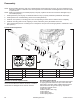
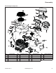
Install Cylinder Heads
NOTE: Match numbers embossed on cylinder heads
and crankcase.
NOTE: When installing cylinder heads, new screws
should always be used. New screws are
supplied in gasket sets.
NOTE: Push rods should always be installed in same
position as before disassembly.
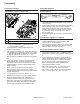
1. Check to make sure there are no nicks or burrs on
sealing surfaces of cylinder head or crankcase.
Make sure dowel locating pins are in lower 2 cylinder
bolt holes on each side.
2. Install a new cylinder head gasket (with printing up)
on each side.
3. Install each cylinder head and start 4 new screws.
4. Torque screws in 2 stages; fi rst to 22.6 N·m
(200 in. lb.), then fi nally to 41.8 N·m (370 in. lb.),
following sequence.
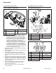
Install Rocker Arms
1. Note mark or tag identifying push rod as either
intake or exhaust and cylinder 1 or 2. Check each
push rod is straight and not bent. Dip ends of push
rods in engine oil and install in their original
positions, making sure each push rod ball seats in its
tappet socket.
2. Install guide plate and studs. Torque studs to
11.3 N·m (100 in. lb.).
3. Apply grease to contact surfaces of adjusters, rocker
arms and rocker arm pivots. Install rocker arms and
rocker arm pivots onto appropriate cylinder head,
and install adjuster fi nger tight. Make sure set screw
is backed out until fl ush with adjuster.