920 Series Sno-Thro® Owner/Operator Manual Manuel Du Propriétaire/Utilisateur Models 920013 – Compact 22 LE (Serial No. 35000 and up) 920014 – Compact 24 LE (Serial No. 35000 and up) Gasoline containing up to 10% ethanol (E10) or up to 10% MTBE (methyl tertiary butyl ether) is acceptable for use in this machine. The use of any gasoline exceeding 10% ethanol (E10) or 10% MTBE will void the product warranty.
TABLE OF CONTENTS SAFETY. . . . . . . . . . . . . . . . . . . . . . . . . . 4 STORAGE . . . . . . . . . . . . . . . . . . . . . . . 32 ASSEMBLY . . . . . . . . . . . . . . . . . . . . . . . 8 SERVICE PARTS . . . . . . . . . . . . . . . . . 33 CONTROLS and FEATURES . . . . . . . . 14 ACCESSORIES. . . . . . . . . . . . . . . . . . . 33 OPERATION . . . . . . . . . . . . . . . . . . . . . 16 TROUBLESHOOTING . . . . . . . . . . . . . 33 MAINTENANCE . . . . . . . . . . . . . . . . . . 22 SPECIFICATIONS .
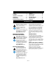
DISCLAIMER Serial Number Label Ariens reserves the right to discontinue, make changes to, and add improvements upon its products at any time without public notice or obligation. The descriptions and specifications contained in this manual were in effect at printing. Equipment described within this manual may be optional. Some illustrations may not be applicable to your unit.
SAFETY PRACTICES AND LAWS WARNING: To avoid injury to hands and feet, always disengage clutches, shut off engine, and wait for all movement to stop before unclogging or working on snow thrower. Hand contact with the rotating impeller is the most common cause of injury associated with snow throwers. Never use your hand to clean out the discharge chute. Keep hands and feet away from auger and impeller. SAFETY ALERTS Look for these symbols to point out important safety precautions.
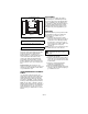
1. DANGER! 2. DANGER! Danger! Danger! ROTATING PARTS! ONLY use clean-out tool to clear blockages. NEVER use your hands. High speed impeller rotates below discharge opening. Wait for all moving parts to stop before removing clogs or servicing. ONLY use clean-out tool to clear blockages. NEVER use your hands. Never direct discharge towards persons or property that may be injured or damaged by thrown objects. 3. DANGER! Keep people away from unit while operating.
EMISSION CONTROL SYSTEM This equipment and/or its engine may include exhaust and evaporative emissions control system components required to meet U.S. Environmental Protection Agency (EPA) and/or California Air Resources Board (CARB) regulations. Tampering with emission controls and components by unauthorized personnel may result in severe fines or penalties. Emission controls and components can only be adjusted by an Ariens Company dealer or an authorized engine manufacturer's service center.
DO NOT overload the machine capacity by attempting to operate or to clear snow at too fast a rate. Slow down and turn corners slowly. Do not operate in reverse unless absolutely necessary. ALWAYS back up slowly. Always look down and behind before and while backing. Disengage attachment drive when traveling from one work area to another. Abnormal Vibrations are a warning of trouble. Striking a foreign object can damage unit. Immediately stop unit and engine. Remove key and wait for all moving parts to stop.
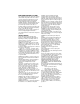
ASSEMBLY 8 WARNING: AVOID INJURY. Read and understand the entire Safety section before proceeding. WARNING: Dropping or tipping over boxed unit could result in personal injury or damage to unit. 7 6 4 5 2 11 PACKAGE CONTENTS PACKAGE CONTENTS Check the contents of your package for the parts listed below (Figure 3): Item Part No. 10 3 12 9 Qty Description The following parts are included as part of the Sno-thro Unit: 1. N/A 1 Sno-thro Unit 2. 07028500 2 3/8 in-16 x 3/4 in.
ASSEMBLY Attach Upper Handlebar Assembly Tools Required: (Figure 5 and 6) 1. Remove handlebar hardware from lower handlebar. Keep hardware. 2. Attach upper handlebar assembly to lower handlebar using two sets of the handlebar hardware removed in step 1. One set to attach each side of the handlebars (Figure 5). IMPORTANT: DO NOT tighten hardware. Allow upper handlebar assembly to hang from the lower handlebars for the next step. • • • • Pliers Open-End Wrenches: 3/8, 7/16, 1/2, 9/16 in.
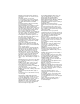
Unfold Upper Handlebar Assembly (Figure 7 and 8) 1. Rotate the handlebar into operating position. NOTE: Be careful not to damage cable spring hooks when rotating handlebar upward. 1 . 1 2 2 5 3 3 1. Attachment Clutch Cable 2. Cable Adjustment Barrel 3. Jam Nut Figure 8 4 OS8255 Connect Headlight Wire Harness 1. 2. 3. 4. 5. (Figure 9) NOTE: The headlight wire harness comes attached to the upper handlebar assembly. 1. Route the wire harness along the interior of the right side of the handlebars.
3. Press cable anchor into mounting hole in the frame near the engine electrical plug. 4. Secure the wire harness to the handlebars using the cable ties attached to the wire harness. Install Discharge Chute (Figure 10) 1. Grease underside of discharge chute ring (if not already greased). 2. Remove mounting hardware from the bottom of the chute pedestal mount. 3. Install discharge chute over opening in the auger housing and secure pedestal to auger housing with hardware removed in step 2.
Install Remote Deflector Cable (920014) . (Figure 12 and 13) 1. Slide cable through clip on top of discharge chute pedestal (Figure 12). 2. Bend clip closed around cable. 3. Using the wire hook attached to the deflector cable, hook cable to discharge chute crank. 5 1 . 4 2 3 6 2 1 3 4 1. Mounting Hole 4. Hairpin 2. Snap Fitting 5. Washer 3. Rubber Seal 6. Cable Eye Cap OS8066 Figure 13 5 1. 2. 3. 4. 5.
Check Tire Pressure Check Auger Gearcase Oil Check tire pressure and adjust to the pressure listed on tire sidewall. Check oil level in auger gearcase (see Check Auger Gearcase on page 23). CAUTION: Avoid injury! Explosive separation of tire and rim parts is possible when they are serviced incorrectly: • Do not attempt to mount a tire without the proper equipment and experience to perform the job. • Do not inflate the tires above the recommended pressure. • Do not weld or heat a wheel and tire assembly.
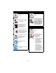
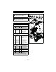
CONTROLS AND FEATURES 18 1 3 2 4 5 6 17 7 16 12 15 9 14 10 8 11 13 Figure 14 1. Attachment Clutch Lever 2. Speed Selector 3. Traction Drive Clutch Lever 4. Chute Crank 5. Muffler Guard 6. Chute Deflector Cap 7. Discharge Chute 8. Impeller 9. Auger 10. Scraper Blade 11. Auger Gearcase 12. Clean-out Tool 13. Skid Shoe(s) 14. Axle Lock Pin 15. Belt Cover 16. Handlebars 17. Headlight 18.
920014 – Briggs & Stratton 920013 – Ariens 1 2 1 2 5 5 11 4 1 7 3 1 4 4 7 3 9 6 8 10 11 9 8 Figure 15 1. Gas Tank and Cap 2. Oil Fill and Dipstick 3. Fuel Shut-off Valve 4. Recoil Starter Handle 5. Electric Starter 6. Throttle 7. Choke 8. Ignition Switch 9. Primer Bulb 10. Engine Shutoff Switch 11.
OPERATION Attachment Clutch – Right Hand Lever WARNING: AVOID INJURY. Read and understand the entire Safety section before proceeding. 2 WARNING: To avoid injury to hands and feet, always disengage clutches, shut off engine, and wait for all movement to stop before unclogging or working on snow thrower. Keep hands and feet away from auger and impeller. CONTROLS AND FEATURES See Figure 14 and 15 for all Controls and Features locations.
Speed Selector Throttle (920014) Position the Speed Selector in the appropriate speed notch to control forward and reverse travel. The throttle controls the engine speed. To increase or decrease the engine speed, adjust to: 1. Fast (normal or warm starts) 2. Part-Throttle 3. Slow (cold weather starts) 4.
3. Remove the snow clean-out tool (1) from the auger housing and use it to remove the clog from the discharge chute. 4. Replace the snow clean-out tool on the auger housing. Wheel Unlocked Discharge Chute Deflector ALWAYS position discharge chute deflector at a safe angle before starting engine. DO NOT throw snow any higher than necessary. Push deflector handle forward or down to throw snow lower. Pull deflector handle up or to the rear to throw snow higher.
FILLING FUEL TANK WARNING: AVOID INJURY. Read and understand the entire Safety section before proceeding. GASOLINE IMPORTANT: ALWAYS use gasoline that meets the following guidelines: • Clean, fresh gasoline. • A minimum of 87 octane/87 AKI (91 RON). High altitude use may require a different octane. Consult your engine manual. • Gasoline with up to 10% ethanol (gasohol) or up to 10% MTBE (methyl tertiary butyl ether) is acceptable.
8. Check Skid Shoes Check and adjust skid shoes (Skid Shoes on page 25). Allow 1/8 in. (3 mm) between scraper blade and hard, smooth surface(s). Allow 7/8 in. (22 mm) between scraper blade and uneven or gravel surfaces. 9. Check Engine Fuel & Crankcase Oil WARNING: AVOID INJURY. Read and understand the entire Safety section before proceeding. Check and add fuel if required. Check that the engine crankcase oil is full using dipstick. Refer to Engine Manual for detailed instructions.
IMPORTANT: DO NOT operate starter more than 15 seconds per minute, as overheating and damage can occur. (If engine does not start, refer to TROUBLESHOOTING on page 33.) 11. Adjust choke as needed. 12. Disconnect power cord from outlet, then starter. 13. 920014 – Set throttle to Part Throttle or Slow position for adaptation to outside temperature or travel. Set throttle to Fast position for normal operation. Tips for Operation Shut Off To travel from one work area to another: 1.
MAINTENANCE Ariens Dealers will provide any service or adjustments which may be required to keep your unit operating at peak efficiency. Should engine service be required, contact an Ariens dealer or an authorized engine manufacturer's service center. The chart below shows the recommended maintenance schedule that should be performed on a regular basis. More frequent service may be required. MAINTENANCE SCHEDULE WARNING: AVOID INJURY. Read and understand the entire Safety section before proceeding.
CHECK CLUTCH OPERATION Auger / impeller must stop within 5 seconds when attachment clutch/impeller brake lever is released. Wheels must stop quickly when traction drive clutch lever is released. If clutches do not engage or disengage properly, adjust or repair before operation (see Attachment Clutch/Brake Adjustment on page 27 and Attachment Drive Belt Replacement on page 29). CLEAN ENGINE Refer to Engine Manual for detailed instructions.
Grease Oil Figure 21 GB - 24 OS8200
SERVICE AND ADJUSTMENTS SHEAR BOLTS WARNING: AVOID INJURY. Read and understand the entire Safety section before proceeding. (Figure 23) SCRAPER BLADE IMPORTANT: Damage to housing will result if blade wears down too far. Scraper blade is adjustable to compensate for wear. To adjust scraper blade: 1. Tip unit back onto handlebar, support housing and loosen nuts retaining blade. 2. Reposition scraper blade and tighten lock nuts. 3. Adjust skid shoes.
MANUAL DISCHARGE CHUTE DEFLECTOR (920013) (Figure 24) Deflector must stay in selected position while throwing snow. To adjust, loosen then retighten the wing knob to desired tension. If deflector does not follow full range of travel: 1. Push deflector remote all the way forward. 2. Loosen adjusting nuts on remote deflector cable attached to the chute deflector (Figure 26). 3. To adjust the deflector lower: Loosen bottom adjustment nut and tighten top adjustment nut.
SPEED SELECTOR ADJUSTMENT 3 (Figure 28) To adjust: 1. Disconnect adjustment pivot pin from speed selector arm. Save hardware for reinstallation. 2. Place the speed selector on dash panel in the fastest forward speed position. 3. Turn the speed selector arm straight down towards the ground as far as it will go. 4. Thread the adjustment pivot pin along the shift rod until it aligns with the mating hole on the speed selector arm, and then turn it up the shift rod 7 turns. Insert the pivot pin into hole. 5.
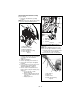
Check Attachment Idler Arm Roller Clearance (Figure 31 and 32) 1. Place the unit into the service position. Remove the bottom cover. 2. With the attachment clutch lever engaged, check the clearance between the frame and plastic roller on the lower end of the attachment idler arm (Figure 31). 1 Roller should be 1/2 – 7/8 in. (12.7 – 22.2 mm) from the frame when the attachment clutch is engaged. 2 3 Figure 31 • 1. Attachment Clutch Cable 2. Cable Adjustment Barrel 3. Jam Nut Figure 29 • OS8255 4.
Check Attachment Brake Check belt finger clearance here. With the attachment clutch engaged, there should be less than 1/8 in. (3,2 mm) clearance between the belt and the belt finger. The belt finger should not touch the belt. (Figure 33) 1. With the clutch lever disengaged, brake pad must contact attachment belt. With clutch lever engaged, brake pad must be more than 1/16 in. (1.6 mm) from belt. If there is more than 1/16 in. (1.6 mm) gap, go to Check Belt Finger Clearance on page 29.
IMPORTANT: To avoid bending bottom cover, when tipping unit apart, support handlebars firmly or tip unit up on housing and remove bottom cover by removing six cap screws before separating unit. 8. Support Sno-Thro frame and housing. 9. Remove hex bolts securing housing to frame (two on each side). Tip housing and frame apart on pivot pin. 10. Separate housing from unit. 11. Remove attachment drive belt from attachment pulley. 1 3 6. Replace chute crank and secure with hairpin.
TRACTION DRIVE BELT REPLACEMENT (Figures 38) NOTE: Housing and frame must be tipped apart and attachment drive belt removed from engine sheave in order to change traction drive belt. CAUTION: Always support Sno-Thro frame and blower housing when loosening the cap screws holding them together. Never loosen cap screws while unit is in service position. 1. Remove attachment drive belt (See Remove Attachment Drive Belt on page 29). 2. Remove swing gate spacer. 3.
4 STORAGE 8 WARNING: AVOID INJURY. Read and understand the entire Safety section before proceeding. 7 SHORT TERM 3 IMPORTANT: NEVER spray unit with high pressure water or store unit outdoors. Run with attachment clutch engaged a few minutes after each use to free unit of any loose or melting snow. Close fuel shut-off valve. Inspect unit for visible signs of wear, breakage or damage. Keep all nuts, bolts and screws properly tightened and know unit is in safe working condition.
Add Fuel Stabilizer 1. Turn the fuel valve off while engine is running and allow the engine to run until it stops. Turn engine OFF when it begins surging to avoid engine damage. 2. Add fuel stabilizer, following the manufacturer’s instructions. 3. Turn fuel valve on after adding fuel stabilizer. 4. Re-start engine. 5. Run the engine outdoors for 1 minutes to be sure that treated gasoline has replaced the untreated gasoline in the carburetor. 6. Slow the engine to an idle speed. 7. Repeat step 1 above.
TROUBLESHOOTING PROBLEM Engine stops. PROBABLE CAUSE 1. Out of fuel. 2. Fuel shut-off valve closed. 3. Mechanical jam in blower rake or impeller. CORRECTION 1. Fill fuel tank (see FILLING FUEL TANK on page 19). 2. Open fuel shut-off valve. 4. Polluted fuel supply. 5. Faulty spark plug. 6. Plugged fuel cap vent. 3. Turn off engine, remove key, and wait for all moving parts to stop. Check for and remove obstruction and repair before restart. 4. Replace with clean fuel. 5. Replace or clean spark plug. 6.
SPECIFICATIONS Model Number 920013 Description Compact 22 Engine Ariens OHV Gross Torque* – lbf-ft (N•m) 9.5 (12.88) *Engine output stated in gross torque per SAE J1940 as rated by engine manufacturer. Displacement – in. (cc) 12.7 (208) High Idle – RPM (min) 3600 ± 100 Electric Start 120V Fuel Tank Capacity – qt (Liters) 2.7 (2.55) Headlight Yes Chute Chute Rotation Angle 205° Rotation Control 2.5X Quick Turn Deflector Control Manual Auger Snow Clearing Width – in. (cm) 22.0 (55.
SPECIFICATIONS Model Number 920014 Description Compact 24 Engine Briggs & Stratton Polar Force Gross Torque* – lbf-ft (N•m) 9.0 (12.2) *Engine output stated in gross torque per SAE J1940 as rated by engine manufacturer. Displacement – in. (cc) 12.5 (205) High Idle – RPM (min) 3600 ± 100 Start 120 V Fuel Tank Capacity – qt (Liters) 2.9 (2.7) Headlight Yes Chute Chute Rotation Angle 205° Rotation Control 2.5X Quick Turn Deflector Control Remote Auger Snow Clearing Width – in. (cm) 24.
Sno-Thro®, Sno-Tek® and Chore Performing Equipment Limited Warranty Ariens Company (Ariens) warrants to the original purchaser that Ariens, Gravely, Parker, and Countax ® ® brand chore performing equipment (including Sno-Thro and Sno-Tek equipment) purchased on or after 1/1/2011 will be free from defects in material and workmanship for the time period noted in the chart below.
Exceptions and Limitations The chart below details special exceptions to this warranty: Warranty Code Warranty Exception Warranty Period Use Detail All Batteries 1 Year All All Belts, Muffler, Tires None Commercial These components are not covered when used commercially. All Cloth, Plastic, and Rubber Components (Including Belts and Cables) Maximum 2 Years All Warranty is limited to 2 years for consumer use. (1 year for warranty code "PD".
Exclusions - Items Not Covered by This Warranty • Parts that are not genuine Ariens, Gravely, Parker or Countax service parts are not covered by this warranty and may void the warranty. • Damages resulting from the installation or use of any part, accessory, or attachment which is not approved by the Ariens Company for use with product(s) identified herein are not covered by this warranty.
CALIFORNIA AND EPA (UNITED STATES ENVIRONMENTAL PROTECTION AGENCY) EVAPORATIVE EMISSION CONTROL WARRANTY STATEMENT YOUR WARRANTY RIGHTS AND OBLIGATIONS The CARB (California Air Resources Board), the EPA, and Ariens Company are pleased to explain the evaporative emission control system's warranty on your 2011 model year small off-road equipment. In California, new equipment that uses small off-road engines must be designed, built, and equipped to meet the State's stringent anti-smog standards.
(4.) (5.) (6.) (7.) (8.) (9.) Repair or replacement of any warranted part under the warranty provisions of this article must be performed at no charge to the owner at an authorized Ariens, Gravely, or Parker service representative. Notwithstanding the provisions of subsection (4) above, warranty services or repairs must be provided at authorized Ariens, Gravely, or Parker service representatives that are franchised to service the subject small off-road equipment.
Ariens 655 West Ryan Street Brillion, WI 54110-1072 920-756-4688 www.ariens.