® Compact Series Sno-Thro Owner/Operator Manual Manuel du Propriétaire/Utilisateur Models 920013 – Compact 22 LE (SN 123000 +) 920021 – Compact 24 LE (SN 000101 +) 920022 – Compact 24 LET (SN 000101 +) E10 The use of any gasoline exceeding 10% ethanol (E10) or 10% MTBE will void the product warranty. L’utilisation d’une essence contenant plus de 10% d’éthanol (E10) ou de 10% de MTBE annulent la garantie.
TABLE OF CONTENTS SAFETY. . . . . . . . . . . . . . . . . . . . . . . . . . 4 STORAGE . . . . . . . . . . . . . . . . . . . . . . . 36 ASSEMBLY . . . . . . . . . . . . . . . . . . . . . . . 8 SERVICE PARTS . . . . . . . . . . . . . . . . . 37 CONTROLS and FEATURES . . . . . . . . 12 ACCESSORIES. . . . . . . . . . . . . . . . . . . 37 OPERATION . . . . . . . . . . . . . . . . . . . . . 15 TROUBLESHOOTING . . . . . . . . . . . . . 37 MAINTENANCE . . . . . . . . . . . . . . . . . . 21 SPECIFICATIONS .
UNAUTHORIZED REPLACEMENT PARTS Use only Ariens replacement parts. The replacement of any part on this vehicle with anything other than an Ariens authorized replacement part may adversely affect the performance, durability, or safety of this unit and may void the warranty. Ariens disclaims liability for any claims or damages, whether warranty, property damage, personal injury or death arising out of the use of unauthorized replacement parts. To locate your nearest Ariens Dealer, go to www.ariens.
SAFETY WARNING: To avoid injury to hands and feet, always disengage clutches, shut off engine, and wait for all movement to stop before unclogging or working on snow thrower. Hand contact with the rotating impeller is the most common cause of injury associated with snow throwers. Never use your hand to clean out the discharge chute. Keep hands and feet away from auger and impeller. SAFETY DECALS AND LOCATIONS ALWAYS replace missing or damaged Safety Decals. Refer to Figure 2 for safety decal locations.
3. DANGER! Stop engine, remove key, read manual before making any repairs or adjustments. Danger! Read Owner/Operator Manual. ROTATING PARTS. Keep clear of auger while engine is running. • Read Operator’s Manual. • Allow operation only by properly trained adult, never children. • Stop engine and remove ignition key prior to leaving the operator’s position for any reason. • Keep all controls, guards and safety devices properly serviced and functional.
DO NOT allow adults to operate unit without proper training. Only trained adults may operate unit. Training includes actual operation. Keep area of operation clear of all toys, pets, and debris. Thrown objects can cause injury. Check for weak spots on docks, ramps or floors. Avoid uneven work areas and rough terrain. Stay alert for hidden hazards. DO NOT operate near drop-offs, ditches, or embankments. Unit can suddenly turn over if a wheel is over the edge of a cliff or ditch, or if an edge caves in.
Run unit a few minutes after clearing snow to prevent freeze-up of attachment. Disengage attachment when not in use. Disengage all clutches before starting engine. Adjust skid shoes to clear gravel or crushed rock surfaces safely. Never leave a running unit unattended. ALWAYS shut off engine before leaving unit. ALWAYS remove key to prevent unauthorized use. Never carry passengers. Check clutch and brake operation frequently. Adjust and service as required.
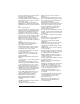
ASSEMBLY Unfold Handlebar ASSEMBLY WARNING: AVOID INJURY. Read and understand the entire Safety section before proceeding. WARNING: Dropping or tipping over boxed unit could result in personal injury or damage to unit. (Figure 4) 1. Remove the lower and loosen the upper hardware on the handlebar assembly. 2. Loosen the hardware on the shift rod. 3. Put speed selector lever in the sixth forward position. 4. Rotate the handlebars into operating position.
INSTALL DISCHARGE CHUTE AND DISCHARGE CHUTE CRANK (Figures 5 and 6) 1. Grease underside of discharge chute ring (if not already greased). 2. Remove mounting hardware from auger housing. 3. Install discharge chute over opening in the auger housing. Finger tighten the mounting hardware removed in step 2. NOTICE: Leave discharge chute pedestal loose to help install the chute crank. 7. Replace gear cover on top of chute pedestal. 8.
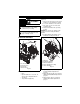
Install Remote Deflector Cable Models 920021, 022 5. Attach cable eye to pin on bottom of deflector control lever. NOTICE: Hold down chute deflector cap, if needed, for more cable slack. 6. Secure cable eye to control lever with bushing and hairpin. 7. Using the wire hook attached to the deflector cable, hook cable to discharge chute crank. 8. Install cable into clip on top of discharge chute pedestal (Figure 8). (Figures 7 and 8) 1. Pull rubber seal cap away from snap fitting (Figure 7). . .
Check Tire Pressure Models 920013, 021 Run-in Attachment Belt Check tire pressure and adjust to the pressure listed on tire sidewall. CAUTION: Avoid injury! Explosive separation of tire and rim parts is possible when they are serviced incorrectly: • Do not attempt to mount a tire without the proper equipment and experience to perform the job. • Do not inflate the tires above the recommended pressure. • Do not weld or heat a wheel and tire assembly.
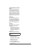
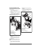
CONTROLS AND FEATURES Model 920013 3 1 Model 920021 2 16 20 3 4 18 2 1 17 4 5 19 6 7 16 12 17 9 15 14 10 8 13 11 Figure 9 1. Attachment Clutch Lever 2. Speed Selector 3. Traction Drive Clutch Lever 4. Discharge Chute Crank 5. Muffler Guard 6. Remote Discharge Chute Deflector (Model 920021) 7. Discharge Chute 8. Impeller 9. Auger 10. Scraper Blade 11. Auger Gearcase 12. Clean-out Tool 13. Skid Shoe(s) 14. Axle Lock Pin 15. Belt Cover 16. Handlebar 17. Headlight 18.
Model 920022 3 17 1 2 4 5 18 6 19 7 15 12 16 14 9 10 8 11 13 Figure 10 1. Attachment Clutch Lever 2. Speed Selector 3. Traction Drive Clutch Lever 4. Discharge Chute Crank 5. Muffler Guard 6. Remote Discharge Chute Deflector 7. Discharge Chute 8. Impeller 9. Auger 10. Scraper Blade 11. Auger Gearcase 12. Clean-out Tool 13. Skid Shoe(s) 14. Belt Cover 15. Handlebar 16. Headlight 17. Remote Deflector Control 18. Remote Chute Deflector Cable 19.
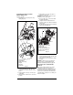
2 1 5 1 4 6 3 10 8 Figure 11 1. Gas Tank and Cap 2. Oil Fill and Dipstick 3. Fuel Shut-off Valve 4. Recoil Starter Handle 5. Electric Starter 6. Choke 7. Ignition Switch 8. Primer Bulb 9. Oil Drain Plug 10.
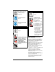
OPERATION WARNING: AVOID INJURY. Read and understand the entire Safety section before proceeding. WARNING: To avoid injury to hands and feet, always disengage clutches, shut off engine, and wait for all movement to stop before unclogging or working on snow thrower. Keep hands and feet away from auger and impeller. IMPORTANT: If the belt squeals continuously when the attachment clutch lever is engaged, the impeller may be frozen in the auger housing.
Fuel Shut-Off Valve IMPORTANT: The fuel shut-off valve MUST be in the closed position prior to transporting the unit. The fuel shut-off valve has two positions: OFF Open (1): Use this 2 position to run the unit. 1 ON 1 Closed (2): Use this position to service, transport, or store the unit. Choke Control 1. Choke Closed position: chokes off air to engine 1 for easier start. 2. Choke Open position: allows for normal operation. IMPORTANT: Gradually open choke after engine starts.
Remote Discharge Chute Deflector Control Models 920021, 022 Wheel Unlocked ALWAYS position discharge chute deflector at a safe angle before starting engine. DO NOT throw snow any higher than necessary. Place deflector remote in a forward notch to throw snow lower. Place deflector remote in a rearward notch to throw snow higher. IMPORTANT: If Chute Deflector does not stay in set position, adjust as directed in SERVICE AND ADJUSTMENTS on page 26, or repair before operation.
GASOLINE Normal Up Position (Transport) Down Position Figure 14 Scraper Blade The scraper blade allows the back of the housing to keep better contact with the surface being cleared. It also prevents damage to the housing from wear. IMPORTANT: DO NOT allow Scraper Blade to wear too far or Auger/Impeller housing will become damaged. Skid Shoes The skid shoes control the distance between the scraper blade and the ground. Adjust skid shoes equally to keep blade level with the ground.
IMPORTANT: DO NOT OVERFILL! This equipment and/or its engine may include evaporative emissions control system components, required to meet EPA and/or CARB regulations, that will only function properly when the fuel tank has been filled to the recommended level. Overfilling may cause permanent damage to evaporative emissions control system components. Filling to the recommended level ensures a vapor gap required to allow for fuel expansion.
Manual Start 1. Turn discharge chute straight ahead. 2. Make sure that the attachment clutch and traction drive clutch levers are fully disengaged. 3. Push primer bulb 2 or 3 times for cold engine. NOTICE: When temperature is below -15° F (-26° C) additional priming may be needed. 4. If engine is cold, apply choke. See Engine Manual for detailed instructions. NOTICE: A warm engine requires less choking than a cold engine. 5. Toggle ignition switch to "Run." 6.
TRAVELING TRANSPORT To travel from one work area to another: 1. Models 920013, 021 – Press down on handlebars enough to raise front of unit slightly off surface. Model 920022 – Place the unit in the Up (Transport) position (see Track Angle on page 17). 2. Engage traction drive clutch without engaging attachment clutch. ALWAYS shut off engine, remove key, and close fuel shut-off valve when transporting unit on a truck or trailer. Use extra care when loading or unloading unit onto trailer or truck.
MAINTENANCE SCHEDULE The chart below shows the recommended maintenance schedule that should be performed on a regular basis. More frequent service may be required. MAINTENANCE SCHEDULE Service Performed Each Every Every Yearly Use 5 hrs. 25 hrs. If clutches do not engage or disengage properly, adjust or repair before operation. See Attachment Clutch/Brake Adjustment on page 28 and Traction Drive Clutch Adjustment on page 31.
To ensure adequate lubricant level: 1. Remove oil fill plug and seal washer (Figure 16). Lubricant must be 1.63 – 1.88" (4.14 – 4.78 cm) from the flat surface of the gear case cover. IMPORTANT: DO NOT remove the gear case cover. 2. Check oil level with suitable dipstick device. Add lubricant if required. NOTICE: Inspect seal washer for wear or rubber deterioration and replace as needed. IMPORTANT: Use only Ariens L3 synthetic severe duty gear lube (Part Number 00068800).
GENERAL LUBRICATION (Figures 18 and 19) IMPORTANT: Wipe each fitting clean before and after lubrication. IMPORTANT: DO NOT allow grease or oil to get on friction disc, friction plate or belts. NOTICE: Apply Ariens Hi-Temp Grease or equivalent to the lubrication fittings. See SERVICE PARTS on page 37. Sno-Thro should be lubricated at beginning of season or every 25 operating hours. Auger Shaft NOTICE: To grease auger shaft, remove shear bolt nuts and shear bolts.
Model 920022 Grease Oil 2x Figure 19 EN - 25
SERVICE AND ADJUSTMENTS SHEAR BOLTS WARNING: AVOID INJURY. Read and understand the entire Safety section before proceeding. SCRAPER BLADE IMPORTANT: Damage to housing will result if blade wears down too far. Scraper blade is adjustable to compensate for wear. To adjust scraper blade: 1. Tip unit back onto handlebar, support housing and loosen nuts retaining blade. 2. Lower scraper blade to compensate for wear then tighten nuts. 3. Adjust skid shoes.
MANUAL DISCHARGE CHUTE DEFLECTOR . Model 920013 (Figure 22) Deflector must stay in selected position while throwing snow. To adjust, loosen then retighten the wing knob to desired tension. Adjustment Nut Figure 23 1 If deflector does not follow full range of travel: 1. Push deflector remote all the way to rear most position. 2. Loosen adjusting nuts on remote deflector cable attached to the chute deflector (Figure 24). 3.
DISCHARGE CHUTE e. Shift speed selector into first reverse speed. f. Engage the traction drive clutch. Unit should move backward. g. Shut off unit. 7. Adjust pivot pin on the shift rod as necessary so unit travels forward when speed selector is in first forward position and travels backward when speed selector is in first reverse position. 8. Connect the pivot pin to the speed selector arm with the hardware removed in step 1.
Remove Attachment Cable Slack (Figures 27 and 28) 1. Shut off engine, remove key, disconnect spark plug wire and allow unit to cool completely. 2. Loosen hardware securing belt cover to unit. NOTICE: DO NOT completely remove the hardware from unit. 3. Remove belt cover. 4. Loosen jam nut on cable adjustment barrel, and then turn the adjustment barrel down to shorten cable and remove all cable slack (Figure 27). With the attachment clutch disengaged, check the attachment idler arm position here.
• • • If roller is 1/2 – 7/8" (12.7 – 22.2 mm) from frame, no further adjustment is required. If roller is less than 1/2" (12.7 mm) from frame, loosen idler adjustment nut and move idler closer to the belt. Tighten adjustment nut and recheck the roller clearance (Figure 30). If roller is more than 7/8" (22.2 mm) from frame, loosen idler adjustment nut and move idler away from the belt. Tighten adjustment nut and recheck roller clearance (Figure 30). Minimum of 1/16" (1.6 mm) 2 Figure 31 2 1 1 1.
5. Remove spring clip pin from chute crank and separate. 6. Models 920021, 022 – Remove remote deflector control cable from control lever. 7. Remove belt finger by removing cap screws mounting belt finger to engine (Figure 34). 8. Remove attachment drive belt from engine sheave (it may be necessary to turn engine sheave using recoil starter handle). Check belt finger clearance here. With the attachment clutch engaged, there should be less than 1/8" (3.2 mm) clearance between the belt and the belt finger.
Replace Attachment Drive Belt 2 1. Place new belt onto attachment pulley (Figure 34). NOTICE: Engage attachment clutch lever while connecting housing to frame to hold brake out of the way. 2. Tip housing and frame back together and secure with hex bolts. 3. Place belt onto engine sheave. 4. Replace belt finger. IMPORTANT: With the attachment clutch lever engaged, the belt finger located opposite the belt idler must be less than 1/8" (3.
TRACTION DRIVE BELT REPLACEMENT (Figure 36) NOTICE: Housing and frame must be tipped apart and attachment drive belt removed from engine sheave in order to change traction drive belt. CAUTION: Always support Sno-Thro frame and blower housing when loosening the cap screws holding them together. Never loosen cap screws while unit is in service position. 1. Remove attachment drive belt (See Remove Attachment Drive Belt on page 31). 2. Detach traction idler spring. 3. Remove swing gate spacer. 4.
Models 920013, 021 4 8 1 7 2 3 3 9 2 1 5 5 4 1. 2. 3. 4. 5. 6. 6 10 Traction Drive Clutch Cable Adjustment Barrel Jam Nut Adjustment Pivot Pin Speed Selector Arm Attachment Clutch Arm Figure 37 6. Remove spring clip pin nearest drive gear from hex shaft. 7. Remove left bearing flange from frame. 8. Slide hex shaft to the left to remove the flat washer, pinion gear and friction disc assembly from the hex shaft.
TRACK TENSION ADJUSTMENT Model 920022 4 Model 920022 (Figures 40 and 41) Check the track tension by applying pressure on the track midway between the upper and rear track rollers. Deflection should be approximately 3/8" (9.5 mm) (Figure 40). If deflection is excessive, tighten the track tension. 9 7 3/8" (9.5 mm) 3 1 5 2 6 8 3 2 1 5 10 1. Hex Shaft 2. Friction Disc Assembly 3. Left Bearing Flange 4. Speed Selector Arm 5. Friction Disc 6. Right Bearing Flange 7. Carrier Bearing 8.
HEIGHT ADJUSTER CABLE ADJUSTMENT Model 920022 (Figure 42) 1. Make sure that height adjustment lock finger is fully engaged (Figure 42). 2. Loosen jam nuts on cable mount bracket. 3. Adjust the jam nuts to remove all cable slack and bring the overtravel arm into slight contact with the right end of the slot in the height adjuster lock finger. 4. Tighten the jam nuts. Pin on overtravel arm makes slight contact with end of slot.
SERVICE PARTS ACCESSORIES Order the following parts through your Dealer: Part No. See your authorized Ariens dealer to add the additional accessories available to your Sno-Thro model. Description Part No. 00036800 Ariens Hi-Temp Grease (Three 3-oz.
TROUBLESHOOTING PROBLEM Does not operate in Forward / Reverse. PROBABLE CAUSE 1. Friction disc worn out. 2. Traction belt not functioning. 3. Speed selector not adjusted properly. CORRECTION 1. Replace friction disc (see Friction Disc Replacement on page 33). 2. Repair or replace traction drive belt (see Traction Drive Belt Replacement on page 33). 3. Adjust speed selector (see Speed Selector Adjustment on page 28). Small rubber beads collect in frame 1. Friction disc wear. 1.
SPECIFICATIONS Model Number Description 920013 920022 920021 Compact 22 Compact 24 Track Compact 24 Engine Ariens AX Gross Torque* – lbf-ft (N•m) 9.5 (12.9) *Engine output stated in gross torque per SAE J1940 as rated by engine manufacturer. Displacement – in. (cc) 12.7 (208) High Idle – RPM (min) 3600 ± 50 Electric Start 120V Fuel Tank Capacity – qt (Liters) 2.9 (2.7) Headlight Yes Chute Chute Rotation Angle 205° Rotation Control Deflector Control 2.
Sno-Thro®, Sno-Tek® and Chore Performing Equipment Limited Warranty Ariens Company (Ariens) warrants to the original purchaser that Ariens, Gravely, Parker, and Countax ® ® brand chore performing equipment (including Sno-Thro and Sno-Tek equipment) purchased on or after 1/1/2013 will be free from defects in material and workmanship for the time period noted in the chart below.
Exceptions and Limitations The chart below details special exceptions to this warranty: Warranty Code Warranty Exception Warranty Period Use Detail All Batteries 1 Year All All Belts, Muffler, Tires None Commercial These components are not covered when used commercially. All Cloth, Plastic, and Rubber Components (Including Belts and Cables) Maximum 2 Years All Warranty is limited to 2 years for consumer use. (1 year for warranty code "PD".
Exclusions – Items Not Covered by This Warranty • Parts that are not genuine Ariens, Gravely, Parker or Countax service parts are not covered by this warranty and may void the warranty. • Damages resulting from the installation or use of any part, accessory, or attachment which is not approved by the Ariens Company for use with product(s) identified herein are not covered by this warranty.
Ariens 655 West Ryan Street Brillion, WI 54110 920-756-4688 Fax 920-756-2407 www.ariens.com www.ariens.com.