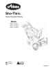
Sno-Thro ® Owner/Operator Manual Models 921001 – ST824E 921002 – ST1027LE 921003 – ST1130DLE 921004 – ST924DLE ENGLISH FRANÇAIS 00660400 6/07 Printed in USA
TABLE OF CONTENTS SAFETY . . . . . . . . . . . . . . . . . . . . . . . . . . . . . . . . . . 3 STORAGE . . . . . . . . . . . . . . . . . . . . . . . . . . . . . . . 29 ASSEMBLY . . . . . . . . . . . . . . . . . . . . . . . . . . . . . . . 7 SERVICE PARTS. . . . . . . . . . . . . . . . . . . . . . . . . . 29 CONTROLS and FEATURES . . . . . . . . . . . . . . . . 11 ACCESSORIES . . . . . . . . . . . . . . . . . . . . . . . . . . . 29 OPERATION . . . . . . . . . . . . . . . . . . . . . . . . . . . . .
DELIVERY WARNING: Improper assembly or adjustments can cause serious injury. Customer Note: If you have purchased this product without complete assembly and instruction by your retailer, it is your responsibility to: 2. Understand all Safety Precautions provided in the manuals. 1. Read and understand all assembly instructions in this manual. If you do not understand or have difficulty following the instructions, contact your nearest Ariens Dealer for assistance.
SAFETY DECALS AND LOCATIONS ALWAYS replace missing or damaged Safety Decals. Refer to figures below for Safety Decal locations. Stop engine, remove key, read manual before making any repairs or adjustments. OL4010 921002, 003, 004 Wear appropriate hearing protection. 1 2 OL4690 08000134 ONLY use clean-out tool to clear blockages. NEVER use your hands. 3 2. DANGER! Figure 2 OS7016 921001 1 OS6610 ROTATING PARTS! ONLY use clean-out tool to clear blockages. NEVER use your hands.
ALWAYS check overhead and side clearances carefully before operation. ALWAYS be aware of traffic when operating along streets or curbs. DO NOT throw snow any higher than necessary. Keep children and people away. Keep children out of work area and under watchful care of a responsible adult. Always stand clear of the discharge area when operating this unit. Deflected materials can cause injury and property damage. NEVER allow children to operate or play on or near unit.
Never carry passengers. Check clutch and brake operation frequently. Adjust and service as required. All motion of drive wheels and auger/impeller must stop quickly when control levers are released. DO NOT operate on steep slopes. DO NOT clear snow across the face of slopes. Keep all movement on slopes slow and gradual. DO NOT make sudden changes in speed or direction. Use a slow speed to avoid stops or shifts on slopes. Avoid starting or stopping on a slope.
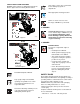
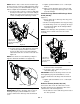
ASSEMBLY 921001 WARNING: AVOID INJURY. Read and understand the entire Safety section before proceeding. 3 2 WARNING: Dropping or tipping over boxed unit could result in personal injury or damage to unit. 1 PACKAGE CONTENTS 921002, 003, 004 3 4 2 1. Sno-Thro Unit 2. Discharge Chute 1 4 3. Chute Rod 4. Literature Pack with Extra Shear Bolts Figure 5 OS7021 ASSEMBLY Tools Required: • Pliers • Open-End Wrenches: 3/8, 7/16, 1/2, 9/16 in.
NOTE: Leave discharge chute pedestal loose to help install the chute rod and connect it to the control assembly. . 921001 4 3 2 1 1 1. Handlebar 2. Wing Knobs and Bolts 3. Wing Nuts and Bolts 4. Speed Selector Lever Figure 6 2 3 OS7032 4 . 921002, 003, 5 004 1 1 4 1 2, 3 1. Mounting Hardware 2. Discharge Chute 3. Chute Pedestal 4. Discharge Chute Ring Figure 8 OS7040 OS7045 4. Remove the cover from the gear assembly on the discharge chute. 1. Wing Knobs 2. Wing Nut 3. Bolt 5.
11. Tighten pedestal hardware to 15 – 31 lbf-ft (20 – 42 N•m). NOTE: After the chute rod has been inserted through the hex hole in the control assembly, placing the unit in the service position (see Service Position on page 18) will ease alignment and installation of the hair pin. 8. Secure the chute rod to the control assembly with the hair pin removed in step 6. Insert the hair pin with the loop end to the left of the chute rod so the control assembly follows a full range of travel. 12.
2. Insert the barrel on the cable end into the bracket on left side of chute deflector (Figure 12). CAUTION: Avoid injury! Explosive separation of tire and rim parts is possible when they are serviced incorrectly: • Do not attempt to mount a tire without the proper equipment and experience to perform the job. 3. Hold seal out of the way while routing the cable through the bracket on the left side of the discharge chute, and then push the cable fitting into the bracket. 4.
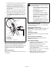
CONTROLS AND FEATURES 1. Attachment Clutch Lever 921001 2. Speed Selector 3 3. Traction Drive Clutch Lever 2 1 4 4. Chute Control 6 5. Oil Fill/Dipstick 6. Discharge Chute Deflector 7. Discharge Chute 7 25 8. Impeller 9. Clean-Out Tool 9 5 10. Auger 8 11. Scraper Blade 23 12. Auger Gearcase 13. Recoil Starter Handle 14. Electric Starter 22 15. Wing Knobs 11 21 16 18 14 20 12 10 16. Ignition Key, Push-Pull 17. Oil Drain Plug 13 18. Throttle (Engine Stop) 19. Choke Control Knob 20.
1. Attachment Clutch Lever 4 18 3 5 2. Speed Selector 921002, 003, 004 3. Deflector Remote Control 2 1 4. Chute Control 7 5. Traction Drive Clutch Lever 6. Oil Fill/Dipstick 17 29 7. Discharge Chute Deflector 8 8. Discharge Chute 28 10 9 6 9. Impeller 10. Clean-Out Tool 11. Auger 26 12. Auger Gearcase 13. Scraper Blade 14. Recoil Starter Handle 11 25 13 12 15. Electric Starter 16. Wing Knobs 17. Heated Handles (921003) 22 21 24 15 18. Remote Wheel Lock (921002) 14 19.
OPERATION Ignition Switch (Push/Pull Safety Key) WARNING: AVOID INJURY. Read and understand the entire Safety section before proceeding. Key Switch has two positions: 1. “Stop” - pulled out WARNING: To avoid injury to hands and feet, always disengage clutches, shut off engine, and wait for all movement to stop before unclogging or working on snow thrower. Keep hands and feet away from auger and impeller. 2 NOTE: DO NOT twist key after it is 1 inserted.
3. Remove the snow clean-out tool (1) from the auger housing and use it to remove the clog from the discharge chute. Choke Control Knob 1.Choke Closed position: chokes off air to engine for easier start. 1 2 2.Choke Open position: allows for normal operation. Place deflector remote in a forward notch to throw snow lower. Place deflector remote in a rearward notch to throw snow higher. Throttle 1 2 1.
Discharge Chute Control (921002, 003, 004) Remote Wheel Lock (921002) IMPORTANT: If chute does not stay in set position, adjust as directed in SERVICE AND ADJUSTMENTS on page 21, or repair before operation. Squeeze and release the remote wheel lock to lock the left wheel for better traction when throwing snow or to unlock the left wheel for easier steering. Rotate the Chute with Discharge Chute Control. NOTE: The wheel lock will not release when under load. Do not unlock the wheel while turning.
FILLING FUEL TANK 3. If Impeller is frozen, (cannot pull Starter Handle) move unit to a heated area and thaw to prevent possible damage. WARNING: AVOID INJURY. Read and understand the entire Safety section before proceeding. 2. Check Function of Clutches If clutches do not engage or disengage properly, adjust or repair before operation. See Attachment Clutch/Brake Adjustment on page 24 and Traction Drive Clutch Adjustment on page 26).
STARTING AND SHUT OFF 5. Push Primer Bulb 2 or 3 times for cold engine. NOTE: When temperature is below -15° F (-26° C) additional priming may be needed. WARNING: FAILURE TO FOLLOW INSTRUCTIONS could result in personal injury and/or damage to unit. DO NOT attempt to start your unit at this time. Read entire Owner/Operator Manual and the Engine Manual first. 6. Insert key into ignition switch on engine and push into "Run" position. DO NOT twist key after it is inserted. 7. If engine is cold, apply choke.
TRAVELING TRANSPORT To travel from one work area to another: ALWAYS shut off engine, remove key, and close fuel shut-off valve when transporting unit on a truck or trailer. 1. Set Throttle to Slow or Part-Throttle position. 2. Press down on handlebars enough to raise front of unit slightly off surface. 3. Engage wheel drive clutch without engaging attachment drive clutch. Use extra care when loading or unloading unit onto trailer or truck. Secure unit chassis to transport vehicle.
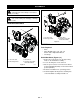
CLEAN ENGINE Refer to Engine Manual for detailed instructions. 1 CHECK ENGINE OIL The engine crankcase oil should be checked every 5 hours of operation. Oil level MUST be maintained in safe operating range on dipstick at all times or engine damage will result (See Engine Manual). 2 Park unit on a level surface. Refer to Engine Manual for detailed instructions. 1. Auger Gearcase 2.
921002, 003, 004 921002 921003, 004 921001 Grease Oil Figure 23 OS7136 OS7141 OS7142 OS7143 GB - 20
SERVICE AND ADJUSTMENTS WARNING: AVOID INJURY. Read and understand the entire Safety section before proceeding. 1 SCRAPER BLADE IMPORTANT: Damage to auger/impeller housing will result if blade wears down too far. Scraper blade is adjustable to compensate for wear. To adjust scraper blade: 1. Tip unit back onto handlebar, support housing and loosen nuts retaining blade 1. Auger 2. Shear Bolts 2. Adjust runners to fully raised position (housing closest to ground).
921002, 003, 004 Tighten nut. 1 2 3 No Slack 1. Top Jam Nut 2. Bottom Jam Nut 3. Cable Adjuster Figure 26 OS7170 DEFLECTOR REMOTE (921002, 003, 004) 1 Deflector must stay in selected position while throwing snow. 2 1. Adjusting Nuts 2. Cable Support Bracket If deflector does not stay in set position: 1. Tighten nut beneath control panel to increase pressure on deflector control (Figure 27). If deflector does not follow full range of travel: 1. Push deflector remote all the way forward.
If chute does not rotate freely: 921001 Tighten the cable by loosening the upper adjustment nut, and then tightening the lower adjustment nut against the bracket (Figure 29). 921002, 003, 004 1 Loosen upper adjustment nut. 2 Tighten lower adjustment nut. 1 Figure 29 OS7180 1. Spring 2. Nut DISCHARGE CHUTE DEFLECTOR (921001) Deflector must stay in selected position while blowing snow 2 Figure 31 OS7177 SPEED SELECTOR ADJUSTMENT To adjust (Figure 32): 1.
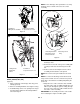
3. With the attachment clutch disengaged, check that the attachment idler arm lightly touches the frame. See Figure 34. 4 1 With the attachment clutch disengaged, check the attachment idler arm position here. The attachment idler arm should lightly touch the frame. 3 1. Shift Rod 2. Adjustment Pivot Pin 3. Speed Selector Lever 4. Hairpin Figure 32 2 OS7186 ATTACHMENT CLUTCH/BRAKE ADJUSTMENT Figure 34 (Figures 33, 34 and 35) OS7194 4. Tighten jam nut on the adjustment barrel.
1/2 – 9/16 in. (12.7 –- 14.3 mm) OS7183 OS7184 Figure 36 2. Adjust attachment idler position. See Figure 37. Roller should be a minimum of 1/2 in. (12.7 mm) from the frame when the attachment clutch is engaged. Figure 35 a. Loosen idler adjustment nut. b. To increase spring extension, move idler closer to belts and tighten adjustment nut. Return to Step 1. c. To decrease spring extension, move idler away from belts and tighten adjustment nut. Return to Step 1.
Check Attachment Brake Check belt finger clearance here. With the attachment clutch engaged, there should be less than 1/8 in. (3 mm) clearance between the belts and the belt finger. The belt finger should not touch the belts. See Figure 38. 1. With the clutch lever disengaged, brake pad must contact attachment belts. With clutch lever engaged, brake pad must be more than 1/16 in. (1.6 mm) from belts. If there is more than 1/16 in. (1.6 mm) gap, go to Check Belt Finger Clearance on page 26.
3. Rotate discharge chute all the way to the left (as viewed from the operator’s position). b. Turn the adjuster body up the cable to decrease the distance between the clutch lever and handlebar. c. Turn the adjuster body down the cable to increase the distance between the clutch lever and handlebar. 4. 921002, 003, 004: Remove hair pin under the control panel connecting the discharge chute rod from the chute rotation lever and slide the discharge chute rod forward.
2. Tip housing and frame back together and secure with hex bolts. 3. Place belt onto engine sheave. 4. Reposition and secure belt fingers. IMPORTANT: With clutch lever engaged, belt finger on the side opposite the belt idler should be less than 1/8 in. (3 mm) from belt, but not touching the belt. Adjust belt finger as necessary. 7 2 2 3 5 1 1 3 7 6 6 4 5 1. Traction Drive Belt 2. Engine Sheave 3. Attachment Drive Belts 4. Belt Finger 4 5. Attachment Belt Idler 6. Attachment Idler Adjustment Nut 7.
5. Disconnect pivot pin from the speed selector arm. Save the hardware for reinstallation. Run with attachment clutch engaged a few minutes after each use to free unit of any loose or melting snow. 6. Remove spring clip pin nearest drive sprocket from hex shaft. Close fuel shut-off valve. Inspect unit for visible signs of wear, breakage or damage. 7. Remove left bearing flange from frame. Keep all nuts, bolts and screws properly tightened and know unit is in safe working condition. 8.
TROUBLESHOOTING PROBLEM Engine will not crank/start. Engine stops. PROBABLE CAUSE CORRECTION 1. Fuel tank is empty. 1. Fill fuel tank. 2. Fuel shut-off valve closed. 2. Open fuel shut-off valve. 3. Build up of dirt and residue around governor/carburetor. 3. Clean area around governor/carburetor. 4. Key Switch not in run position. 4. Put Key Switch into run position. 5. Electric starter not functioning. 5. Check for a bad starter or connections. 1. Out of fuel. 1. Fill fuel tank. 2.
SPECIFICATIONS Model Number 921001 921002 921003 921004 ST824E ST1027LE ST1130DLE ST924DLE Engine - Tecumseh LH318SA Tecumseh LH358SA Tecumseh LH358SA Tecumseh LH318SA Power Max - HP (kW) 8.0 (5.97) 10.0 (7.46) 11.0 (8.20) 9.25 (6.90) 21.8 (358) 19.4 (318) Description Fast Idle Speed - RPM (min-1) 3600 ± 150 Displacement - in. (cc) 19.4 (318) 21.8 (358) Electric Start 120V Fuel See Engine Manual Tank Capacity - qt (Liters) Snow Clearing Width - in. (cm) 4 (3.8) 24 (61.
Ariens Limited Warranties 2-Year Limited Lawn and Garden Consumer Warranty Ariens Company (Ariens) warrants to the original purchaser that Ariens and Gravely brand consumer products manufactured by Ariens Company will be free from defects in material and workmanship for a period of two (2) years after the date of purchase, and that Ariens will repair any defect in material or workmanship, and repair or replace any defective part, subject to the conditions, limitations and exclusions set forth herein.
Exceptions, Limitations, Exclusions These warranties are subject to the following conditions, limitations, and exclusions: To obtain warranty service, the following conditions must be met: The following items are excluded from this warranty: • The purchaser must perform the maintenance and minor adjustments explained in the owner’s manual. • Engines and engine accessories are covered only by the engine manufacturer’s warranty and are not covered by this warranty.
Ariens Company 655 West Ryan Street Brillion, WI 54110-1072 920-756-2141 Fax 920-756-2407 www.ariens.