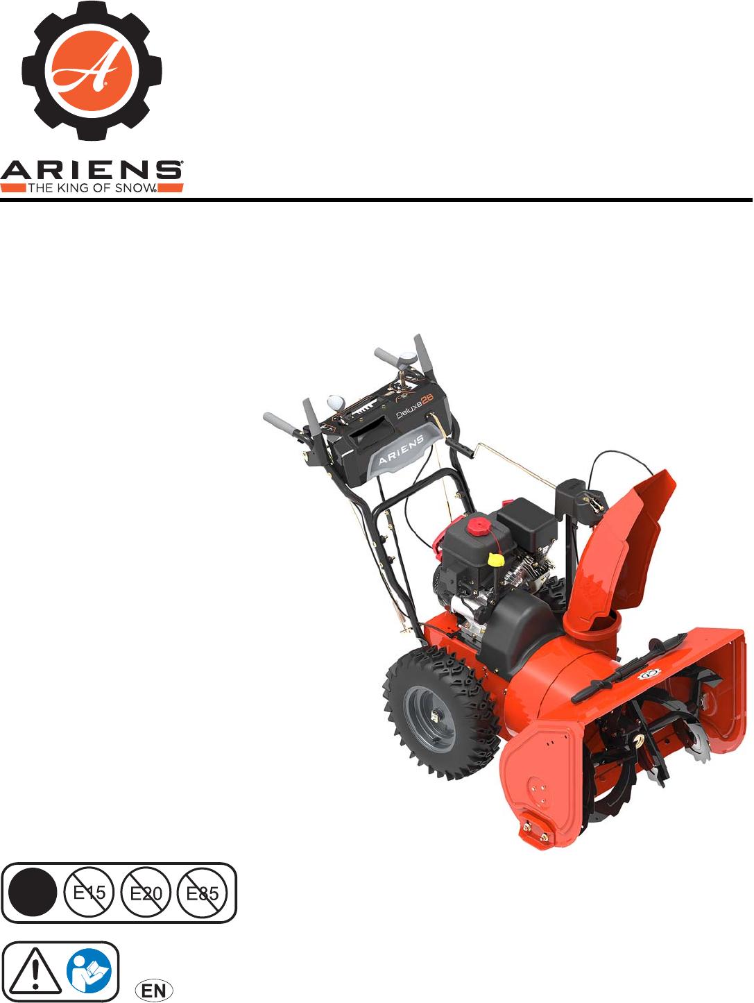
® Sno-Thro Service Guide Deluxe Series Models 921045 – Deluxe 24 (SN 000101 +) 921046 – Deluxe 28 (SN 000101 +) 921047 – Deluxe 30 (SN 000101 +) 921048 – Deluxe 28 SHO (SN 000101 +) 921049 – Deluxe 30 EFI (SN 000101 +) 921323 – Deluxe 24 CE (SN 000101 +) 921324 – Deluxe 28 CE (SN 000101 +) 921325 – Deluxe 30 CE (SN 000101 +) 921326 – Deluxe 28 Track CE (SN 000101 +) E10 ENGLISH 05001330D • 1/17
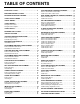
TABLE OF CONTENTS PRACTICES & LAWS . . . . . . . . . . . . . . . . . . . . . . . . . . 2 TRACTION DRIVE CABLE REPLACEMENT. . . . . . . . 31 EMISSION CONTROL SYSTEM . . . . . . . . . . . . . . . . . . 2 Remove Traction Drive Clutch Cable . . . . . . . . . . . . . . . . . . . 31 Install Traction Drive Clutch Cable . . . . . . . . . . . . . . . . . . . . . 32 REQUIRED OPERATOR TRAINING. . . . . . . . . . . . . . . 2 DUAL-HANDLE INTERLOCK CAM REPLACEMENT . 33 SAFETY ALERT SYMBOL . . . . . . . . . . . . .
TROUBLE CODE DIAGNOSTICS. . . . . . . . . . . . . . . . . 61 Code 16: Low Battery Voltage . . . . . . . . . . . . . . . . . . . . . . . . Code 21: Barometer Sensor . . . . . . . . . . . . . . . . . . . . . . . . . . Code 22: Engine Temperature Sensor . . . . . . . . . . . . . . . . . . Code 27: Low Fuel Pressure. . . . . . . . . . . . . . . . . . . . . . . . . . Code 28: High Battery Voltage . . . . . . . . . . . . . . . . . . . . . . . . 61 62 62 63 64 DIAGNOSTICS FOR NON-TROUBLE CODES. . . . . . .
WELCOME Before operating or servicing the unit, carefully and completely read the Operator’s Manual and engine manual provided with the unit at time of purchase. They contain important safety instructions and information about unit controls. Have Questions or Need Assistance? ariensstore.com (Dealer Locator) ariens.custhelp.com (Self-Support) A parts manual and an operator’s manual for your unit are available for free download or purchase at ariens.com.
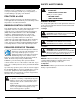
SAFETY ALERT SYMBOL SAFETY Read these safety rules and follow them closely. Failure to follow these rules could lead to loss of control of unit, severe personal injury or death to you or bystanders, or result in damage to property or the machine. This is the safety alert symbol. It means: PRACTICES & LAWS • BECOME ALERT! Practice usual and customary safe working precautions. Learn applicable rules and laws in your area. Always follow the practices set forth in this manual.
SAFETY DECALS Stop engine, remove key, and read manual before making any repairs or adjustments. The safety decals on your machine are visual reminders of the important safety information in this manual. All messages on your unit must be fully understood and carefully followed. Safety decals on the machine are explained below. Read Operator’s Manual. Always replace missing or damaged safety decals. Replacement decal information is in the parts manual for your machine.
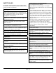
SAFETY RULES Handle fuel with care; it is highly flammable. The following safety instructions are based on the B71.3 specifications of the American National Standards Institute in effect at the time of production. • Use an approved fuel container. Training Read, understand and follow all instructions on the machine and in the manual(s) before operating this unit. Be thoroughly familiar with the controls and the proper use of the equipment. Know how to stop the unit and disengage the controls quickly.
After striking a foreign object, stop the engine, remove the wire from the spark plug, disconnect the cord on electric motors, thoroughly inspect the snow thrower for any damage, and repair the damage before restarting and operating the snow thrower. If the unit should start to vibrate abnormally, stop the engine and check immediately for the cause. Vibration is generally a warning of trouble.
Always refer to operator's manual for important details if the snow thrower is to be stored for an extended period. Never fill fuel containers inside a vehicle or on a truck or trailer bed with a plastic liner. Always place containers on the ground away from your vehicle before filling. Maintain or replace safety and instruction labels as necessary. When practical, remove gas-powered equipment from the truck or trailer and refuel it on the ground.
DRAINING FUEL SYSTEM SEPARATE HOUSING FROM FRAME 1. Move unit to an open, well-ventilated area with no flames or sparks. Remove Auger Housing 2. Remove fuel tank cap and siphon fuel into a clean gasoline container. IMPORTANT: Save all hardware for reinstallation. 1. Stop engine, remove key and wait for moving parts to stop and for hot parts to cool. 3. Reinstall fuel tank cap and tighten. 2. Disconnect spark plug wire from engine. 4.
See Figure 4. 2. Remove hairpin and cable eyelet from chute control assembly. 3. With a pliers, squeeze tabs on cable snap and remove from chute control assembly. 4. Guide cable end through lower hole in chute control assembly and through hole in dash panel. Models 921045, 921046, 921047, 921048, 921049, 921323, 921324, 921325 7. Remove spring clip from chute rotation rod and remove rod from chute gears. See Figure 5.
See Figure 8. All Models See Figure 6. 9. Remove hairpin, sleeve bushing and cable eyelet from deflector arm under dash panel. 10. With a pliers, squeeze tabs on cable snap and remove from deflector anchor. 12. Remove tapping screw securing left side of belt cover to frame. 13. Loosen, but DO NOT remove tapping screw securing right side of belt cover to frame and remove belt cover. IMPORTANT: Reinstall sleeve bushing and hairpin so parts are not misplaced. 1 2 4 5 3 1. 2. 3. 4. 5.
WARNING: AVOID INJURY. Attachment sheave edges are sharp. Wear thick gloves to remove belts from attachment sheave. See Figure 10. 15. Remove attachment drive belts from attachment sheave. To assist belt removal, slowly pull recoil starter handle while gently guiding belts out of attachment sheave. Figure 12 Reinstall Auger Housing See Figure 13. Figure 10 1. With assistance from an adult helper, engage attachment clutch lever so attachment brake will not obstruct attachment drive pulley in step 2. 2.
3. Release attachment clutch lever. 4. Align holes in mount brackets with holes in frame and secure housing to frame with two hex bolts, but DO NOT tighten. IMPORTANT: Unit must be on a flat, level surface during steps 5 – 7. 5. Check tire pressure and adjust if necessary. Refer to Operator’s Manual for specification. 6. Torque hex bolts installed in step 4 to 33.8 – 70.1 N•m (24.9 – 51.7 lb-ft). 7. Loosen skid shoe hardware and adjust skid shoes. Refer to Operator’s Manual for adjustment procedure.
22. Reinstall deflector cable snap onto deflector anchor. 23. Remove sleeve bushing and hairpin from deflector arm and reinstall cable eyelet onto deflector arm. Reinstall sleeve bushing and hairpin. See Figure 6.Reconnect spark plug wire. BOTTOM COVER REMOVAL IMPORTANT: Save all hardware for reinstallation. WARNING: AVOID INJURY. Before placing unit in service position, drain fuel from tank and fuel system. See Draining Fuel System on page 7. Make sure unit is secure and will not tip.
ATTACHMENT DRIVE BELT REPLACEMENT Remove Attachment Drive Belts IMPORTANT: Save all hardware for reinstallation. 1. Stop engine, remove key and wait for all moving parts to stop and for hot parts to cool. 2. Disconnect spark plug wire from engine. 3. Remove auger housing. See Separate Housing From Frame on page 7. 4. Remove attachment drive belts from attachment drive pulley. See Figure 18. Figure 17 Install Bottom Cover 1.
TRACTION DRIVE BELT REPLACEMENT See Figure 21. Remove Traction Drive Belt 6. Disconnect idler spring from traction idler arm. 7. Remove stop bolt from frame. IMPORTANT: Save all hardware for reinstallation. 1. Stop engine, remove key and wait for all moving parts to stop and for hot parts to cool. 2. Disconnect spark plug wire from engine. 3. Remove belt cover and belt finger as shown in Figure 8 and Figure 9. 4.
Install Traction Drive Belt 6. Check belt finger clearance: • Engage attachment clutch lever and make sure belt finger located opposite belt idler is less than 3.2 mm (1/8") from belt, but not touching the belt. See Figure 23. 1. Install belt onto traction sheave and around traction drive pulley. 2. Return swing gate assembly to upright position and reinstall stop bolt. 3. Reinstall traction idler spring onto traction idler arm.
ATTACHMENT BRAKE REPLACEMENT See Figures 26 and 27. Remove Attachment Brake 3. IMPORTANT: Save all hardware for reinstallation. 1. Stop engine, remove key and wait for all moving parts to stop and for hot parts to cool. 2. Disconnect spark plug wire from engine. 3. Remove auger housing. See Separate Housing From Frame on page 7. Engage and disengage attachment clutch to verify brake roller on attachment idler does not interfere with brake pad. IMPORTANT: Make sure brake roller does not bind.
WARNING: AVOID INJURY. Before placing unit in service position, drain fuel from tank and fuel system. See Draining Fuel System on page 7. Make sure unit is secure and will not tip. 5. FRICTION DISC REPLACEMENT Remove Friction Disc IMPORTANT: Save all hardware for reinstallation. WARNING: AVOID INJURY. Before placing unit in service position, drain fuel from tank and fuel system. See Draining Fuel System on page 7. Make sure unit is secure and will not tip.
1 2 3 1. Bearing Flange 2. Hex Shaft 3. Bearing 8. Figure 32 Figure 30 Remove two spring clips from hex shaft. See Figure 31. Figure 31 9. Remove hex shaft from friction disc assembly and remove friction disc assembly. See Figure 32.
Install Friction Disc 1. Install friction disc assembly around shift fork roller bearing and align with hex shaft. See Figure 33. Figure 35 Figure 33 2. Reinstall hex shaft through friction disc, pinion sprocket and into frame. See Figure 34. 6. Reinstall adjustment pivot pin onto shift arm and secure with hairpin. 7. Reinstall bottom cover and secure with two tapping screws and four hex bolts. 8. Reinstall wheels onto axle and secure with snap clips. 9. Return unit to operating position. 10.
HEX SHAFT BEARING REPLACEMENT SWING GATE REPLACEMENT Remove Bearing Remove Swing Gate Assembly IMPORTANT: Save all hardware for reinstallation. 1. Stop engine, remove key and wait for all moving parts to stop and for hot parts to cool. IMPORTANT: Save all hardware for reinstallation. 1. Stop engine, remove key and wait for all moving parts to stop and for hot parts to cool. 2. 2. Disconnect spark plug wire from engine. 3. Remove auger housing. See Separate Housing From Frame on page 7. 4.
See Figure 38. 7. Disconnect traction drive clutch cable and return spring from swing gate. IMPORTANT: To gain more cable slack, traction drive clutch cable may need to be removed from traction clutch lever. See Figure 69. 2 1 Figure 40 Install Swing Gate Assembly 1. Traction Drive Clutch Cable 2. Return Spring Figure 38 8. Remove three hairpins and one flat steel washer from pivot rod and remove pivot rod. See Figure 39. WARNING: AVOID INJURY.
AUGER REPLACEMENT Remove Auger IMPORTANT: Save all hardware for reinstallation. 1. Stop engine, remove key and wait for all moving parts to stop and for hot parts to cool. 2. Disconnect spark plug wire from engine. 3. Remove auger housing. See Separate Housing From Frame on page 7. See Figure 43. CAUTION: AVOID INJURY. Attachment drive pulley edges are sharp. Wear gloves when handling pulley.
7. Remove hardware retaining support bushings to auger housing. See Figure 44. Figure 44 Figure 46 8. Remove hardware retaining gearcase support brackets to housing. See Figure 45. 10. Remove shear bolt from auger shaft. See Figure 47. Figure 47 11. Remove support bushing and flange bushing from auger shaft end. See Figure 48. Figure 45 9. Remove auger assembly from housing. See Figure 46.
See Figure 49. 12. Remove auger. Use of penetrating oil or heat may be necessary to remove auger. NOTICE: If rust is present on auger shaft, remove with sand paper and wipe clean with oil. Figure 51 5. Reinstall auger assembly into housing so impeller shaft is seated in ball bearing at housing rear. See Figure 52. Figure 49 Install Auger See Figure 50. 1. Install auger onto auger shaft with auger kickers facing gearcase.
6. Secure support brackets to auger housing with two round head square neck bolts and two top locking flange nuts. See Figure 53. 2 1 1. Spacer Bushing 2. Bearing Plate Figure 53 Figure 55 7. Secure support bushings to auger housing with six tapping screws. See Figure 54. 12. Reinstall housing to frame. See Reinstall Auger Housing on page 10. 13. Reconnect spark plug wire. Figure 54 See Figure 55. 8. Tighten three hex nuts retaining bearing plate. 9.
AUGER GEARCASE REPLACEMENT Remove Gearcase Assembly IMPORTANT: Save all hardware for reinstallation. 1. Stop engine, remove key and wait for all moving parts to stop and for hot parts to cool. 2. Disconnect spark plug wire from engine. 3. Remove augers. See Remove Auger on page 22. See Figure 56. 4. Remove hardware retaining support brackets to gearcase and remove brackets. 5. Remove two flat steel washers from auger shaft. 3 Figure 57 2 1 Install Gearcase Assembly 1.
IMPELLER REPLACEMENT Install Impeller Remove Impeller See Figure 59. IMPORTANT: Save all hardware for reinstallation. 1. Stop engine, remove key and wait for all moving parts to stop and for hot parts to cool. 2. Disconnect spark plug wire from engine. 3. Remove auger housing. See Separate Housing From Frame on page 7. 1. Apply a thin layer of anti-seize to impeller shaft. 2. Install impeller onto impeller shaft. See Figure 58. 4.
ENGINE REPLACEMENT Remove Engine IMPORTANT: Save all hardware for reinstallation. 1. Stop engine, remove key and wait for all moving parts to stop and for hot parts to cool. 2. Disconnect spark plug wire from engine. 3. Drain gasoline from fuel system and tank. See Draining Fuel System on page 7. 4. Remove belt cover. See Figure 8. 5. Remove hardware securing belt finger to engine and remove belt finger. See Figure 9. 6. Disconnect idler spring from traction drive idler arm and remove spring.
Install Engine See Figure 64. 7. Remove hardware securing engine mount to frame. 8. Remove J-clamp and chute deflector cable from engine mount. WARNING: AVOID INJURY. Engine is heavy. NEVER lift engine without a suitable lifting device or adult assistant. 1. Using a suitable lifting device or help from an adult assistant, lift engine and lower onto bolts in frame. 2. Position belts over crankshaft. 3. Reinstall J-clamp to left rear engine mounting position. 4.
11. Reinstall belt finger and secure with two flat steel washers, two locking washers and two hex bolts as shown in Figure 9. See Figure 67. 8. Reinstall idler spring to traction idler arm. 9. Secure attachment sheave to crankshaft with one locking washer and hex bolt. 12. Check belt finger clearance: • Engage attachment clutch lever and make sure belt finger located opposite belt idler is less than 3.2 mm (1/8”) from belt, but not touching the belt.
TRACTION DRIVE CABLE REPLACEMENT Remove Traction Drive Clutch Cable IMPORTANT: Save all hardware for reinstallation. 1. Stop engine, remove key and wait for all moving parts to stop and for hot parts to cool. 2. Disconnect spark plug wire from engine. 3. Loosen traction drive clutch cable. 4. Under dash panel, remove hardware retaining upper traction clutch cable to clutch lever and remove cable. See Figure 69. Figure 70 7. Remove belt cover. See Figure 8. 8.
Install Traction Drive Clutch Cable WARNING: AVOID INJURY. Before placing unit in service position, drain fuel from tank and fuel system. See Draining Fuel System on page 7. Make sure unit is secure and will not tip. 1. Rotate unit to service position and remove bottom cover. See Service Position on page 7 and Bottom Cover Removal on page 12. See Figure 72. 2. Route cable end with spring hook through hole in back cover. 3. Install cable end onto swing gate. Figure 73 6.
DUAL-HANDLE INTERLOCK CAM REPLACEMENT IMPORTANT: Interlock cams will fall from camshafts in next step. 3. Remove hardware retaining camshafts to clutch levers and remove camshafts. See Figure 75. Remove Interlock Cam IMPORTANT: Save all hardware for reinstallation. See Figure 74. Models 921045, 921046, 921048 1. Disconnect spring from interlock bracket. 2. Remove two spring clips securing interlock cams to camshafts.
Install Interlock Cams Models 921045, 921046, 921048 IMPORTANT: Make sure nylon bushings are seated in interlock bracket. See Figure 76. Models 921045, 921046, 921048 Models 921047, 921049, 921323, 921324, 921325, 921326 Models 921047, 921049, 921323, 921324, 921325, 921326 Figure 77 3. Position left interlock cam inside interlock bracket and align with left camshaft. 4. Insert camshaft through cam. 5. Secure camshaft to clutch lever with one tapping screw. Figure 76 1.
See Figure 78. AXLE BUSHING REPLACEMENT 6. Rotate cam so flat edge is positioned upward and secure with spring clip. Remove Left Axle Bushing 7. Reconnect spring to interlock bracket. IMPORTANT: Save all hardware for reinstallation. WARNING: AVOID INJURY. Before placing unit in service position, drain fuel from tank and fuel system. See Draining Fuel System on page 7. Make sure unit is secure and will not tip. Models 921045, 921046, 921048 1.
Remove Right Axle Bushing See Figure 81. IMPORTANT: Save all hardware for reinstallation. IMPORTANT: Two flat steel washers will fall when short axle is removed. 7. Hold differential gear and remove short axle. WARNING: AVOID INJURY. Before placing unit in service position, drain fuel from tank and fuel system. See Draining Fuel System on page 7. Make sure unit is secure and will not tip. 1. Stop engine, remove key and wait for all moving parts to stop and for hot parts to cool. 2.
Install Right Axle Bushing 1. 4. Secure bushing to frame exterior with three tapping screws from inside frame. See Figure 83. Align differential gear with pinion gear and short axle. Reinstall short axle into differential. See Figure 85. Figure 85 Figure 83 See Figure 86. See Figure 84. 5. Reinstall long axle into differential gear. 2. Reinstall short axle until a small portion of axle is through frame. 6. Reinstall E-ring onto axle end. 3. Reinstall two flat steel washers onto axle.
FLANGE BUSHING REPLACEMENT See Figure 88. IMPORTANT: Save all hardware for reinstallation. WARNING: AVOID INJURY. Before placing unit in service position, drain fuel from tank and fuel system. See Draining Fuel System on page 7. Make sure unit is secure and will not tip. 1. Stop engine, remove key and wait for all moving parts to stop and for hot parts to cool. 2. Disconnect spark plug wire from engine. 3. Place unit in service position and remove bottom cover.
Install Flange Bushings DIFFERENTIAL GEAR REPLACEMENT 1. Remove Differential Gear Install flange bushings into pinion gear. See Figure 90. 2. IMPORTANT: Save all hardware for reinstallation. Reinstall pinion gear into chain and align with differential gear. 3. Position sleeve bushing between pinion gear and frame. 4. Reinstall pinion shaft through frame, sleeve bushing and pinion gear. 5. Reinstall one flat steel washer onto pinion shaft. WARNING: AVOID INJURY.
See Figure 93. IMPORTANT: Two flat steel washers will fall when short axle is removed. 7. Hold differential gear in place and remove short axle. 8. Remove differential. Figure 95 See Figure 96. 4. Reinstall long axle into differential gear. 5. Reinstall E-ring onto axle end. Figure 93 Install Differential Gear See Figure 94. 1. Reinstall short axle until a small portion of axle is through frame. 2. Reinstall two flat steel washers onto axle. Figure 96 6.
CHUTE GEAR REPLACEMENT Remove Chute Rotation Gear Models 921045, 921046, 921047, 921048, 921049, 921323, 921324, 921325 IMPORTANT: Save all hardware for reinstallation 1. Stop engine, remove key and wait for all moving parts to stop and for hot parts to cool. 2. Disconnect spark plug wire from engine. See Figure 97. 3. Remove hardware retaining chute gear cover and remove cover. 4. Remove spring clip from chute rotation rod and remove rod from chute gears.
Remove Chute Rotation Gear Model 921326 IMPORTANT: Save all hardware for reinstallation 1. Stop engine, remove key and wait for all moving parts to stop and for hot parts to cool. 2. Disconnect spark plug wire from engine. 3. Position discharge chute facing forward. 3 See Figure 100. 4. Remove hardware retaining chute gear cover and remove cover. 5. Remove hairpin from hex rod and remove hex rod from chute gears. 4 1 2 1 2 1. 2. 3. 4.
2 4 1 1 3 1. Friction Plate 2. Chute Mount Bracket Figure 102 4. Reinstall actuation gear bracket to pedestal plate and secure with two tapping screws. 5. Reinstall chute rotation rod into chute gear and secure with spring clip. 6. Reinstall chute gear cover and secure with tapping screw. 7. Adjust discharge chute. Refer to Operator’s Manual for adjustment procedure. 8. Reconnect spark plug wire. 1. 2. 3. 4. 3.
5. Reinstall hex rod into chute gears and secure with hairpin. 6. Reinstall chute gear cover and secure with tapping screw. 7. Adjust discharge chute. Refer to Operator’s Manual for adjustment procedure. 8. Reconnect spark plug wire. 7. Remove actuation gear from actuation gear bracket. 8. Remove flat steel washer from actuation gear. 1 IMPORTANT: Check all adjustments after first use.
Install Actuation Gear SCRAPER BLADE REPLACEMENT Models 921045, 921046, 921047, 921048, 921049, 921323, 921324, 921325 1. Install one flat steel washer onto actuation gear and insert gear through actuation gear bracket. Remove Scraper Blade 2. Install push nut onto actuation gear so it is tight against actuation gear bracket. 3. Reinstall actuation gear bracket to pedestal plate and secure with two tapping screws. 4. Reinstall chute rotation rod into chute gear and secure with spring clip. 5.
Install Scraper Blade HEADLIGHT REPLACEMENT 1. Position scraper blade inside auger housing and align with holes in housing. Remove Bulb 2. Insert seven flat head square neck bolts through scraper blade from inside housing. Secure with seven top locking flange nuts. 3. Insert two round head square neck bolts through scraper blade ends and skid shoes from inside housing. Secure with two flat steel washers and two hex nuts. 4. Return unit to operating position. 5.
GEARCASE REBUILD Disassemble Gearcase IMPORTANT: Save all parts for reassembly, unless otherwise specified. 1. Remove gearcase. See Remove Gearcase Assembly on page 26. 2. Remove any rust, if present, from auger and impeller shafts with sandpaper. Wipe clean with oil. 3. Remove drain plug and seal washer from gearcase. See Figure 113. Figure 112 Install Bulb NOTICE: DO NOT touch new bulb with bare hands; wear gloves.
See Figure 114. 4. Remove hardware retaining gearcase cover and remove cover. 5. Remove gasket and drain gearcase. Figure 116 9. Figure 114 6. With a flathead screwdriver or similar pry bar, remove front seal cover and discard. See Figure 117. Remove bushing retainer from gearcase. See Figure 115. Figure 117 Figure 115 See Figure 116. 7. Press auger shaft through the right side of gearcase. NOTICE: DO NOT strike auger shaft end; use a press. 8. Remove seal, bushing and washer from auger shaft.
14. Remove seals and flange bushings from gearcase. See Figure 120. 10. With a snap ring pliers, remove retaining ring. See Figure 118. Figure 118 Figure 120 See Figure 119. Assemble Gearcase 11. With a driver, strike impeller shaft end until shaft is through front of gearcase. See Figure 121. NOTICE: DO NOT strike impeller shaft end without using a driver. 1. Press rear seal into gearcase until flush with gearcase exterior. 12. Remove pin and bushing from impeller shaft. 2.
See Figure 122. 4. Reinstall impeller shaft through gearcase front and reinstall thrust collar onto impeller shaft end. 5. Wrap a seal protector over impeller shaft end and reinstall shaft through gearcase seal. Remove seal. NOTICE: Unprotected seals can be damaged when installed over rough edges in shaft, such as holes. Figure 123 Figure 122 8. See Figure 123. 6. Reinstall pin into impeller shaft. Turn shaft so pin is horizontal. 7.
See Figure 127. 13. Reinstall one flat steel washer and bushing onto right auger shaft end. IMPORTANT: Stepped-down side of bushing MUST be positioned toward gearcase. Figure 125 10. Turn impeller shaft by hand to make sure shaft rotates easily. See Figure 126. 11. Reinstall one flat steel washer into left side of gearcase. 12. Align washer with gearcase hole and reinstall auger shaft through gear. IMPORTANT: Make sure auger shaft key aligns with gear keyway. Figure 127 14.
See Figure 129. See Figure 131. 15. Wrap seal protector around each auger shaft end so they cover the shear bolt holes. 20. Reinstall gearcase gasket. NOTICE: Unprotected seals can be damaged when installed over rough edges in shaft, such as holes. 21. Secure cover to gearcase with four external tooth locking washer bolts. 16. Install gearcase seals over seal protectors and press into gearcase until each seal is flush with gearcase exterior. 17. Remove seal protectors.
TRACK DRIVE WHEEL REPLACEMENT Model 921326 Remove Track Drive Wheel IMPORTANT: Save all hardware for reinstallation. WARNING: AVOID INJURY. Before placing unit in service position, drain fuel from tank and fuel system. See Draining Fuel System on page 7. Make sure unit is secure and will not tip. 1. Stop engine, remove key and wait for all moving parts to stop and for hot parts to cool. 2. Disconnect spark plug wire from engine. 3. Place unit in service position. See Service Position on page 7. 4.
TRACK REPLACEMENT Model 921326 Remove Track IMPORTANT: Save all hardware for reinstallation. WARNING: AVOID INJURY. Before placing unit in service position, drain fuel from tank and fuel system. See Draining Fuel System on page 7. Make sure unit is secure and will not tip. 1. Stop engine, remove key and wait for all moving parts to stop and for hot parts to cool. 2. Disconnect spark plug wire from engine. 3. Place unit in service position. See Service Position on page 7. 4. Remove track drive wheel.
Install Track BOGIE WHEEL REPLACEMENT See Figure 137. Model 921326 IMPORTANT: Tracks are directional and MUST be installed with treads in the orientation shown in Figure 137. 1. Install track onto carriage assembly so bogie wheels and track runner are seated in track center. Remove Bogie Wheel 2. IMPORTANT: Save all hardware for reinstallation. WARNING: AVOID INJURY. Before placing unit in service position, drain fuel from tank and fuel system. See Draining Fuel System on page 7.
TRACK BEARING REPLACEMENT Model 921326 Remove Bearing From Left Side of Unit IMPORTANT: Save all hardware for reinstallation. WARNING: AVOID INJURY. Before placing unit in service position, drain fuel from tank and fuel system. See Draining Fuel System on page 7. Make sure unit is secure and will not tip. 1. Stop engine, remove key and wait for all moving parts to stop and for hot parts to cool. 2. Disconnect spark plug wire from engine. 3. Place unit in service position.
3. Reinstall stepped-down end of long axle through side plate, frame and into differential gear. See Figure 144. Figure 144 4. Figure 142 Reinstall E-ring onto axle end. See Figure 145. 11. Remove hardware retaining bearing flange(s) and remove flange(s). IMPORTANT: Bearing plate is not a wear item and does not need replacement unless damaged. 2 Figure 145 1 1. Bearing Flange 2. Bearing Plate Figure 143 Tighten six locking nuts securing mount plates to track carriage. 6.
Remove Bearing From Right Side of Unit IMPORTANT: Save all hardware for reinstallation. WARNING: AVOID INJURY. Before placing unit in service position, drain fuel from tank and fuel system. See Draining Fuel System on page 7. Make sure unit is secure and will not tip. 1. Stop engine, remove key and wait for all moving parts to stop and for hot parts to cool. 2. Disconnect spark plug wire from engine. 3. Place unit in service position. See Service Position on page 7. 4. Remove tracks.
See Figure 149. 11. Remove hardware retaining bearing flange(s) and remove bearing(s). IMPORTANT: Bearing plate is not a wear item and does not need replacement unless damaged. 2 1 Figure 150 1. Bearing Flange 2. Bearing Plate 6. Reinstall long axle into differential gear. See Figure 151. Figure 149 Install Bearing to Right Side of Unit IMPORTANT: Bearing plates are ONLY installed with bearing flanges on frame. Bearing plates are NOT installed with bearings on side plates. 1.
EFI REPLACEMENT COMPONENTS EFI TROUBLE CODE IDENTIFICATION See Figure 152. Model 921049 Ariens recommends using only genuine Ariens replacement parts on this unit. Using unauthorized parts may adversely affect the performance, durability or safety of this unit and may void the warranty. Click the Parts Diagrams by Parts Radar link at www.ariens.
CHECKING TROUBLE CODES TROUBLE CODE DIAGNOSTICS The blinking red LED light on the ECU displays trouble codes. Its sequence indicates a particular system malfunction by blinking as many times as the first digit of a trouble code, pausing, and then blinking as many times as the second digit of a trouble code. NOTICE: Before performing diagnostic tasks, be aware of the screw on the bottom of the throttle body that adjusts the servo offset.
Code 21: Barometer Sensor See Figure 152. This trouble code indicates the barometric pressure sensor has failed. When the barometric sensor fails, the engine will not adjust to altitude changes, but will continue to operate at a default altitude of 800 feet above sea level. Engine may continue to operate with a failed barometric pressure sensor, but may not operate at optimal performance. If barometric pressure sensor fails, replace ECU. Code 22: Engine Temperature Sensor See Figure 152.
Code 27: Low Fuel Pressure See Figure 161. Low fuel pressure is usually a result of an empty fuel tank, but could also be from a clogged fuel filter or faulty fuel pump. 5. Attempt engine start and check for trouble code reoccurrence after each of the following steps. Refer to Operator’s Manual for engine starting instructions. IMPORTANT: Fuel pump voltage MUST be measured within 30 seconds of the ignition switch being turned to the ON position. 1.
DIAGNOSTICS FOR NON-TROUBLE CODES Engine Starts and Loses Power Engine Temperature 1 7 Ext-ANA- (Potentiometer) Potentiometer 2 8 Fuel Pressure Input Servo - 3 9 Servo-Signal Servo + 4 10 Ext-ANA+ (Potentiometer) Red B- 5 11 ECU+ Injector- 6 12 Pump- If the engine starts and loses power immediately, this is usually an indication that the ECU does not detect an RPM signal.
d. With battery voltage between 7.2 – 8.4 volts DC, turn the key to the ON position for 10 seconds to pump fuel into the container. Fuel should measure approximately 160 mL (5 oz.). If fuel amount measures less than 160 mL, remove the fuel pump and check the pre-filter for blockage. If filter is clean, replace fuel pump. See Figure 163. b. Set a multi-meter to volts DC and probe each terminal with the red probe and contact the black probe to engine block.
c. If no voltage is present at the injector, check voltage at both the red and white wires on the12-pin ECU connector. See Figure 166. Figure 167 Surging Run Condition If the AC output wire from the engine charging system is damaged, it may cause an intermittent short. This will result in erratic running such as the engine over revving or “popping” through the exhaust. 1. Check the engine wiring and wiring under the handlebar to verify that it is not damaged.
3. Red Engine Connector 1 14 7 Battery Connector 2 Battery Connector 1 13 6 Engine Connector 2 12 5 Potentiometer 3 11 4 Potentiometer 1 10 3 9 2 8 1 Green Potentiometer 2 Yellow Ignition Key Switch 2 Ignition Key Switch 1 With a multi-meter, measure the volts DC of the green / white wire. See Figure 170. a. With engine off, position the red probe on the terminal of the green / white wire. b. Position the black probe on the engine block. c. Turn ignition key to ON position. d.
SERVICE RECORD DATE SERVICE PERFORMED EN – 68 NOTES
655 West Ryan Street Brillion, WI 54110 ariensstore.com ariens.custhelp.com parts.ariens.