Power Brush 28 Operator’s Manual Manuel du Utilisateur Model 921056 – Power Brush 28 (SN 000101 +) E10 ENGLISH FRANÇAIS 05175100 • 11/17 Printed in USA
TABLE OF CONTENTS WELCOME . . . . . . . . . . . . . . . . . . . . . . 1 SAFETY. . . . . . . . . . . . . . . . . . . . . . . . . 2 Practices & Laws . . . . . . . . . . . . . . . . . . Emission Control System. . . . . . . . . . . . Required Operator Training . . . . . . . . . . Safety Alert Symbol . . . . . . . . . . . . . . . . Signal Words . . . . . . . . . . . . . . . . . . . . . Safety Decals. . . . . . . . . . . . . . . . . . . . . Safety Rules. . . . . . . . . . . . . . . . . . . . . .
WELCOME Congratulations on your purchase and welcome to the Ariens family! Every power brush in the Ariens lineup is designed for long-lasting and unsurpassed performance. We are confident your machine will be part of your family for many years to come. Have Questions or Need Assistance? ariens.custhelp.com • ariensstore.com A service guide and a parts manual for your unit are available for free download or purchase at www.ariens.com.
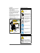
SAFETY WARNING: AVOID INJURY. This unit is capable of crushing or amputating body parts. Failure to observe the safety instructions in the manuals and on decals could result in serious injury or death. Read these safety rules and follow them closely. Failure to follow these rules could lead to loss of control of unit, severe personal injury or death to you or bystanders, or result in damage to property or the unit.
. Important Safety Decal Descriptions IMPORTANT: Indicates general reference information worthy of special attention. 1. WARNING! SAFETY DECALS The safety decals on your unit are visual reminders of the important safety information in this manual. All messages on your unit must be fully understood and carefully followed. Safety decals on the unit are explained below. ALWAYS replace missing or damaged safety decals. Replacement decal information is in the parts manual for your unit.
SAFETY RULES 3. DANGER! The following safety instructions are based on the B71.3 specifications of the American National Standards Institute in effect at the time of production. DANGER! Training Read, understand and follow all instructions on the unit and in the manual(s) before operating this unit. Be thoroughly familiar with the controls and the proper use of the equipment. Know how to stop the unit and disengage the controls quickly. Keep clear of brush while engine is running.
Handle fuel with care; it is highly flammable. • Use an approved fuel container. • NEVER add fuel to a running engine or hot engine. • Fill fuel tank outdoors with extreme care. NEVER fill fuel tank indoors. • NEVER fill containers inside a vehicle or on a truck or trailer bed with a plastic liner. ALWAYS place containers on the ground, away from your vehicle, before filling. • When practical, remove gas-powered equipment from the truck or trailer and refuel it on the ground.
Disengage attachment when not in use and when traveling from one work area to another. Keep unit free of ice or other debris. Clean up oil or fuel spills. ALWAYS keep protective structures, guards, and panels in good repair and secured in place. NEVER modify or remove safety devices. Disengage power to the attachment when unit is transported or not in use. Use only attachments and accessories approved by the manufacturer of the unit (such as wheel weights, counterweights or cabs).
Use a slow speed to avoid stops or shifts on slopes. Avoid starting or stopping on a slope. DO NOT park unit on a slope unless absolutely necessary. When parking on a slope ALWAYS block the wheels. Towing/Transporting DO NOT operate near drop-offs, ditches, or embankments. Unit can suddenly turn over if a wheel is over the edge of a cliff or ditch, or if an edge caves in. Use extra care when loading or unloading unit onto trailer or truck. Secure unit chassis to transport vehicle.
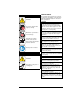
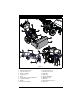
CONTROLS & FEATURES 10 19 9 8 7 20 5 6 11 3 16 2 1 13 14 4 12 15 18 Figure 3 1. 2. 3. 4. 5. 6. 7. 8. 9. 10. Traction Drive Clutch Lever Attachment Clutch Lever Speed Selector Lever Brush Lock Trigger Brush Guard Brush Caster Wheels & Height Adjustment Fuel Tank and Cap Muffler Air Cleaner Assembly 11. 12. 13. 14. 15. 16. 17. 18. 19. 20.
CHOKE CONTROL LEVER WARNING: Read and understand the Safety section before proceeding. See Figure 6. Controls airflow to the engine. See Figure 3 for all controls and features locations. ENGINE KEY See Figure 4. Controls power to the engine. The key cannot be removed when in run position. On Off Figure 6 Stop THROTTLE CONTROL LEVER See Figure 7. Controls engine speed. Run Fast Slow Figure 7 Figure 4 SPEED SELECTOR LEVER FUEL VALVE See Figure 8. Controls the speed of forward and reverse travel.
ATTACHMENT CLUTCH LEVER (RIGHT SIDE) DUAL HANDLE INTERLOCK Allows brush to rotate without holding attachment clutch lever continuously. Brush continues to turn until both clutch levers are released. See Figure 9. Controls brush rotation. AUTO-TURN™ STEERING Automatically locks or unlocks wheels to allow unit to turn more precisely. OPERATION WARNING: AVOID INJURY. Read and understand the Safety section before proceeding.
START THE ENGINE SET BRUSH HEIGHT 1. Electric Start Models: Connect power cord to starter and then into 120V 3-wire grounded outlet. IMPORTANT: Use a power cord that is UL listed or CSA certified, rated for a minimum of 13 amps, grounded and labeled as suitable for outdoor use. All Models 2. Turn fuel valve to on position. 3. Insert engine key and turn to run position. 4. Move choke control lever to on position. 5. Move throttle control lever one-third of the way toward full-throttle. 6.
2. Raise brush: a. Remove lynch pins from caster shaft tops. b. Remove desired amount of height adjuster clips from caster shaft tops and install onto lower caster shaft ends. c. Turn height adjuster clips so they DO NOT align with flat side of caster shafts. d. Reinstall lynch pins. 2 1 3 Figure 14 TRANSPORT UNIT 1. Stop engine and close fuel valve. 2. Secure unit chassis to transport vehicle. NOTICE: NEVER secure from rods or linkages that could be damaged. 1. Lynch Pin 2. Caster Shaft 3.
ADJUST ENGINE AIR CLEANER Normal Position 1. Pull down latches and move tabs away from base to release air cleaner cover. See Figure 15. Winter/Cold Weather Position Figure 15 2. Rotate cover to the winter/cold-weather position or summer position. See Figure 16. NOTICE: DO NOT run engine with air filter cover in the winter/cold-weather position while operating in normal temperatures. Figure 16 3. Position latches under base and lift up on latches until they lock to secure cover.
MAINTENANCE 4 3 2 WARNING: Read and understand the Safety section before proceeding. 6 Your Ariens dealer can provide service and adjustments to keep your unit operating at peak efficiency. Contact an authorized engine manufacturer’s service center for engine service. 1 5 SERVICE POSITION WARNING: AVOID INJURY. Before rotating unit, close fuel valve and drain fuel from tank and fuel system. (Refer to engine manual for insturctions.) Make sure unit is secure and will not tip.
1 2 2 3 1 3 1. Tapping Screw 2. Mount Rod 3. Mount Bracket Figure 20 1. Machine Screw 2. Lock Washer 3. Brush Lock Trigger Figure 19 See Figure 21. CAUTION: AVOID ENGINE DAMAGE. Do not leave unit in service position for longer than 30 minutes. Allow 30 minutes for oil to return to crankcase before starting engine. WARNING: ALWAYS support unit frame and brush attachment when loosening hardware holding them together.
3.2 mm (1/8") 1 3 Figure 22 2 1. Bottom Cover 2. Engine Sheave 3. Engine Figure 21 9. Reinstall belt cover and tighten hardware. 10. Reinstall brush lock trigger onto handlebars and route brush lock cable through J-clamp on engine mount. 11. Adjust attachment clutch / brake. See Adjust Attachment Clutch & Brake on page 19. RETURN UNIT TO OPERATING POSITION 1. Reinstall bottom cover and secure with six tapping screws. 2. Return tractor / frame to operating position and onto a support. 3.
Check Clutch Lever Operation • Check Dual Handle Interlock • Check Fasteners • Clean Recoil Guard Foam Cover • Check Engine Oil • Check Clutch Cable Adjustments * CHECK FASTENERS Check for loose or missing hardware. Annually Every 25 hrs. Every 5 hrs. Service Performed Each Use MAINTENANCE SCHEDULE CHECK CLUTCH CABLE ADJUSTMENTS Brush must stop within 5 seconds when attachment clutch lever is released. Wheels must stop quickly when traction drive clutch lever is released.
IMPORTANT: If cover is clogged with snow, remove it and allow foam to thaw or rinse with warm water. Allow cover to dry before reinstalling. Casters See Figure 24. IMPORTANT: More frequent service may be required in extreme conditions (heavy loads, high ambient temperatures, dusty conditions or airborne debris). LUBRICATE UNIT Ariens recommends using Ariens Hi-Temp Grease or equivalent (see Service Parts on page 17) to lubricate fittings. Lubricate each season or every 25 hours of operation.
6. Connect pivot pin to speed selector arm with hardware removed in step 2 and check forward and reverse speeds. a. Start unit, position speed selector lever in the first forward position and engage traction drive clutch. Unit should move forward. b. Stop unit, position speed selector lever in the first reverse position and engage traction drive clutch. Unit should move in reverse. c. Stop unit. If unit does not travel correctly, repeat adjustments. * 2 4 * 1 Figure 26 3 3.
IMPORTANT: DO NOT completely remove hardware from unit. Check Attachment Idler Arm Roller Clearance 4. Loosen jam nut on cable adjustment barrel, and then turn the adjustment barrel down to shorten cable and remove cable slack. See Figure 28. See Figure 30. 1. Place unit in service position and remove bottom cover. See Service Position on page 14. 2. Engage attachment clutch and check the clearance between the frame and plastic roller on attachment idler arm. Roller should be 12.7 mm – 22.
Check Attachment Brake Check Belt Finger Clearance See Figure 31. 1. Place unit in service position and remove bottom cover. See Service Position on page 14. With the attachment clutch disengaged, brake pad must contact attachment belt or pulley, whichever is closest. With attachment clutch engaged, brake pad must be a minimum of 1.6 mm (1/16") from belt or pulley. • If there is less than 1.6 mm (1/16") gap, loosen idler adjustment nut and move idler away from belt or pulley.
1 2 3 1. Traction Drive Clutch Cable 2. Cable Adjustment Barrel 3. Jam Nut Figure 33 See Figure 34. 4. With traction clutch disengaged, check that swing gate tab touches the front edge of stop hole. IMPORTANT: Swing gate tab MUST touch stop hole edge. Readjust cable as necessary until tab touches stop hole edge. 1 1. Swing Gate Tab Figure 34 5. Reconnect spark plug wire.
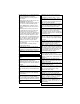
TROUBLESHOOTING Problem Probable Cause Engine key in stop position. Correction Turn engine key to run position. See Engine Key on page 9. Choke is off. Turn choke control knob to on position. See Choke Control Lever on page 9. Fuel valve is closed. Open valve. See Fuel Valve on page 9. Fuel tank is empty. Fill tank with fuel. See Before Operating Unit on page 10. Build up of dirt and residue Clean area around governor / carburetor. Engine will not around governor / carburetor. See your Ariens dealer.
TROUBLESHOOTING Problem Probable Cause Attachment clutch / brake is not adjusted correctly. Debris is caught in brush. Correction See Adjust Attachment Clutch & Brake on page 19. Stop engine and wait for all moving parts to stop and for hot parts to cool. Remove obstruction before restarting. Unit sweeps poorly. Attachment drive belt is slipping, Adjust or replace attachment drive belt. worn or damaged. Refer to the service guide for your unit.
START-OF-SEASON FUEL PREPARATION STORAGE WARNING: AVOID INJURY. Read and understand the Safety section before proceeding. Before opening the fuel valve for the first time after long-term storage, add fresh, stabilizertreated fuel to the fuel tank and any fuel containers with remaining fuel. ACCESSORIES SHORT TERM 1. Tighten all hardware to correct specifications. 2. Inspect unit for visible signs of wear or damage. Repair as needed. 3.
SPECIFICATIONS Model Number 921056 Engine Engine Model Kohler CH255 3 3 177 (10.8) Displacement – cm (in ) Maximum RPM – No Load 3750 ± 100 Starter 120V Electric and Recoil Fuel See Engine Manual Tank Capacity – L (qt) 2.9 (3.1) Brush Clearing Width – cm (in) 71.2 (28) Brush Diameter – cm (in) 45.7 (18) Brush Rotation Speed – RPM 200 Brush Rotation Angle Total 40° (20° left / right) Drive Drive Disc-O-Matic Drive Speeds 6 Forward 2 Reverse Pneumatic Tires – in 16 x 4.
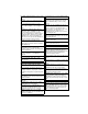
Sno-Thro®, Sno-Tek® and Finishing Tool Equipment Limited Warranty Warranty Ariens Company (Ariens) warrants to the original purchaser that Ariens, Gravely, Parker, and Countax ® ® brand chore-performing equipment (including Sno-Thro and Sno-Tek equipment) purchased on or after 1/1/2016 will be free from defects in material and workmanship for the time period noted in the chart below.
Exceptions and Limitations The chart below details special exceptions to this warranty: Warranty Code Warranty Period Use 1 Year All None Commercial These components are not covered when used commercially. Maximum 2 Years All Warranty is limited to 2 years for consumer use. (1 year for warranty code "PD".) Except as noted above, these components are covered for defect, not for wear. Maximum 2 Years All Warranty is limited on idlers to 2 years for consumer use.
Exclusions – Items Not Covered by This Warranty • Parts that are not genuine Ariens, Gravely, Parker or Countax service parts are not covered by this warranty and may void the warranty. • Damages resulting from the installation or use of any part, accessory, or attachment which is not approved by the Ariens Company for use with product(s) identified herein are not covered by this warranty.
655 West Ryan Street Brillion, WI 54110 ariensstore.com ariens.custhelp.com parts.ariens.