Sno-Thro ® Operator’s Manual Manuel du Utilisateur Platinum Series Models 921050 – Platinum SHO 24 (SN 035000 +) 921051 – Platinum SHO 30 (SN 035000 +) 921057 – Platinum SHO 28 RapidTrak (SN 000101 +) E10 ENGLISH FRANÇAIS 05135900A • 5/18 Printed in USA
TABLE OF CONTENTS WELCOME . . . . . . . . . . . . . . . . . . . . . . 1 Register Your Product!. . . . . . . . . . . . . . 1 SAFETY. . . . . . . . . . . . . . . . . . . . . . . . . 2 Practices & Laws . . . . . . . . . . . . . . . . . . Emission Control System. . . . . . . . . . . . Required Operator Training . . . . . . . . . . Safety Alert Symbol . . . . . . . . . . . . . . . . Signal Words . . . . . . . . . . . . . . . . . . . . . Safety Decals. . . . . . . . . . . . . . . . . . . . . Safety Rules. . . . .
WELCOME Congratulations on your purchase and welcome to the Ariens family! Every snow thrower in the Ariens lineup is designed for long-lasting and unsurpassed performance. We are confident your machine will be part of your family for many years to come. Have Questions or Need Assistance? ariensstore.com • ariens.custhelp.com A service guide and a parts manual for your unit are available for free download or purchase at ariens.com.
SAFETY WARNING: AVOID INJURY. This snow thrower is capable of crushing or amputating body parts. Failure to observe the safety instructions in the manuals and on decals could result in serious injury or death. ALWAYS disengage auger, stop unit and engine, remove key and allow moving parts to stop before leaving operator’s position. Read these safety rules and follow them closely.
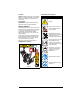
4. Notice Safety Decal Descriptions NOTICE: Indicates information or procedures that are considered important but not hazard related. If not followed, property damage could result. 1. CAUTION! Danger! 5. Important IMPORTANT: Indicates general reference information worthy of special attention. SAFETY DECALS The safety decals on your machine are visual reminders of the important safety information in this manual. All messages on your unit must be fully understood and carefully followed.
SAFETY RULES 2. DANGER! The following safety instructions are based on the B71.3 specifications of the American National Standards Institute in effect at the time of production. Danger! Training ROTATING PARTS! Only use clean-out tool to clear blockages. NEVER use your hands. High-speed auger/impeller rotates below discharge opening. Wait for all moving parts to stop before removing clogs or servicing.
Handle fuel with care; it is highly flammable. • Use an approved fuel container. • Never add fuel to a running engine or hot engine. • Fill fuel tank outdoors with extreme care. Never fill fuel tank indoors. • Never fill containers inside a vehicle or on a truck or trailer bed with a plastic liner. Always place containers on the ground, away from your vehicle, before filling. • When practical, remove gas-powered equipment from the truck or trailer and refuel it on the ground.
Maintenance and Storage Disengage attachment when not in use and when traveling from one work area to another. Secure unit so it will not tip over during maintenance. Disengage power to the auger / impeller when snow thrower is transported or not in use. Before cleaning, removing clogs or making any inspections, repairs, etc., disengage clutch(es), stop engine, remove key, allow moving parts to stop and hot parts to cool.
Personal Protection Never fill or drain fuel tank indoors. Do not operate the equipment without wearing adequate winter garments. Avoid loose fitting clothing that can get caught in moving parts. Wear footwear that will improve footing on slippery surfaces. Replace fuel cap securely and clean up spilled fuel. Wear adequate safety gear, including safety glasses with side shields and protective gloves. Do not wear loose clothing or jewelry, and tie back hair that may get caught in rotating parts.
CONTROLS & FEATURES 15 26 25 24 27 8 12 3 13 23 6 4 8 7 22 20 19 14 28 11 16 17 3 21 5 2 1 9 1. 2. 3. 4. 5. 6. 7. 8. 9. 10. 11. 12. 13. 14. Engine Key Primer Bulb Fuel Tank and Cap Fuel Valve Electric Start Button Choke Control Knob Throttle Control Knob Oil Fill / Dipstick Oil Drain Recoil Starter Handle Speed Selector Lever Auger Impeller Shear Bolt (2) 10 8 Figure 3 15. 16. 17. 18. 19. 20. 21. 22. 23. 24. 25. 26. 27. 28.
CHOKE CONTROL KNOB WARNING: Read and understand the Safety section before proceeding. See Figure 6. Controls airflow to the engine. Off See Figure 3 for all controls and features locations. ENGINE KEY On See Figure 4. Controls power to the engine. The key cannot be removed when in run position. Figure 6 THROTTLE CONTROL KNOB See Figure 7. Controls engine speed. Run Idle Stop Figure 7 Run SPEED SELECTOR LEVER See Figure 8. Controls the speed of forward and reverse travel.
ATTACHMENT CLUTCH LEVER (RIGHT SIDE) DISCHARGE CHUTE ROTATION LEVER See Figure 9. Controls auger / impeller movement. See Figure 11. Rotates discharge chute to control snow discharge. Pull lever back to unlock chute, move lever left or right to desired position, and then push lever forward to lock chute in place. Figure 9 TRACTION DRIVE CLUTCH LEVER (LEFT SIDE) Figure 11 See Figure 10. Allows unit to travel forward and in reverse. DISCHARGE CHUTE DEFLECTOR LEVER See Figure 12.
SKID SHOE OPERATION Controls the distance between the scraper blade and the surface. WARNING: AVOID INJURY. Read and understand the Safety section before proceeding. AUGER Rotates to bring snow into impeller. IMPELLER Throws snow out discharge chute. SHEAR BOLT Secures auger to shaft and helps prevent gearcase and gearcase component damage. AUTO-TURN™ STEERING Automatically locks or unlocks wheels to allow unit to turn more precisely. HEIGHT ADJUSTMENT LEVER (RIGHT SIDE) Model 921057 See Figure 13.
START THE ENGINE Adjust Track Angle 1. Electric Start: Connect power cord to starter and then into 120V 3-wire grounded outlet. Model 921057 See Figure 14. • Wheel Operation: Allows for maximum maneuverability and ease of turning for locations not requiring high traction. Squeeze height adjustment lever and push down on handlebar. Release lever to latch rear track idlers in raised position. • Track Operation: Allows for maximum traction and keeps auger housing level when clearing deep or wet snow.
Clear a Clogged Discharge Chute MAINTENANCE WARNING: NEVER use your hand to clean out discharge chute. 1. Stop engine, remove key and wait for all moving parts to stop and for hot parts to cool. 2. Use the snow clean-out tool to clear the clog. 3. Return the tool to its storage position on the auger housing. WARNING: Read and understand the Safety section before proceeding. Your Ariens dealer can provide service and adjustments to keep your unit operating at peak efficiency.
As Needed CHECK DUAL HANDLE INTERLOCK Annually Every 25 hrs. Every 5 hrs. Service Performed Each Use MAINTENANCE SCHEDULE Add Fuel Stabilizer * 1. Stop engine. 2. Engage attachment clutch and then the traction drive clutch. 3. Release the attachment clutch lever. The attachment clutch should stay engaged until the traction drive clutch lever is released.
CHANGE ENGINE OIL LUBRICATE UNIT Refer to engine manual. Ariens recommends using Ariens Hi-Temp Grease or equivalent (see Service Parts) to lubricate fittings. Lubricate each season or every 25 hours of operation. CHECK AUGER GEARCASE OIL 1. Place unit on flat, level surface. 2. Remove oil fill plug and seal washer. See Figure 16. IMPORTANT: DO NOT remove gearcase cover. IMPORTANT: Wipe each fitting clean before and after lubrication.
Models 921050, 921051 Model 921057 1 2 Figure 19 1. Height Adjuster Plate 2. Height Adjuster Stop Figure 17 Lubricate Unit Use the following key for all lubrication procedures. Oil Grease * = Lubricate on Both Sides 1. Lubricate as shown in Figures 18, 19 and 20. 2. Reinstall bottom cover and return unit to operating position. Model 921057 Figure 20 LUBRICATE AUGER SHAFT 1. Remove shear bolt nuts and bolts. See Figure 21.
ADJUST SKID SHOES 2. Apply grease at the grease zerks. See Figure 22. See Figure 23. 1. Place unit on a hard, flat surface. 2. Place a spacer under each scraper blade end. • Use two 3 mm (1/8") thick spacers for hard, smooth surfaces. • Use two 22 mm (7/8") thick spacers for uneven or gravel surfaces. 3. Loosen skid shoe hardware and lower skid shoes to contact surface. Adjust both shoes equally. Figure 22 3. Hand rotate auger on auger shaft. 4.
See Figure 21. 1. Align shear bolt holes in auger with shear bolt holes in the shaft. 2. Insert bolts through holes. 3. Secure bolts with nuts. 4. Tighten bolts to 7.9 N•m – 16.5 N•m (5.8 lb-ft – 12.2 lb-ft). If a torque wrench is unavailable, tighten bolts until they no longer spin freely. DO NOT overtighten. 1 ADJUST DISCHARGE CHUTE DEFLECTOR LEVER 2 See Figure 25. If deflector does not stay in selected position, tighten the nut under the control panel. 3 1. Chute Cable 2. Upper Adjustment Nut 3.
1 1 4 3 3 2 1. 2. 3. 4. 4 1. 2. 3. 4. Discharge Chute Gear Cover Rear Adjustment Nut Forward Adjustment Nut Lock Arm Figure 27 2 Shift Rod Adjustment Pivot Pin Speed Selector Arm Hairpin Figure 28 ADJUST ATTACHMENT CLUTCH & BRAKE ADJUST SPEED SELECTOR LEVER See Figure 28. 1. Disconnect adjustment pivot pin from speed selector arm. Save hardware for reinstallation. 2. Position speed selector lever in fastest forward position. 3. Turn speed selector arm down as far as it will go. 4.
Check Attachment Idler Arm Roller Clearance 1 1. Place unit in service position and remove bottom cover. 2. Engage attachment clutch and check the clearance between the frame and plastic roller on the lower end of the attachment idler arm. Roller should be 12.7 mm – 22.2 mm (1/2" – 7/8") from the frame. See Figure 31. 2 3 2 1. Attachment Clutch Cable 2. Cable Adjustment Barrel 3. Jam Nut Figure 29 5. With the attachment clutch disengaged, make sure auger idler arm lightly touches the frame.
• If there is less than 1.6 mm (1/16") gap, loosen idler adjustment nut and move idler away from belt or pulley. Position idler to achieve a 1.6 mm (1/16") minimum brake pad gap and a 12.7 mm – 22.2 mm (1/2" – 7/8") gap between the plastic roller and the frame. See Figure 32. 2 IMPORTANT: If adjustments cannot be brought into specified ranges, see your dealer for repair. 1 3 Check Belt Finger Clearance 1. Idler 2. Belt 3. Pulley See Figure 34.
ADJUST HEIGHT ADJUSTMENT CABLE 1 Model 921057 See Figure 37. 2 3 NOTICE: Make sure height-adjuster lock finger is fully engaged before making adjustments. 1. Loosen jam nuts on cable adjustment barrel. 2. Tighten right jam nut to remove slack between adjustment barrel and cable eyelet. 3. Tighten left jam nut. 1. Traction Drive Clutch Cable 2. Cable Adjustment Barrel 3. Jam Nut Figure 35 1 4. With traction clutch disengaged, check that the drive plate touches the stop bolt. See Figure 36. 6 1. 2. 3.
TROUBLESHOOTING Problem Probable Cause Engine key in stop position. Choke is off. Fuel valve is closed. Fuel tank is empty. Engine is not primed. Correction Turn engine key to run position. See Engine Key on page 9. Turn choke control knob to on position. See Choke Control Knob on page 9. Open valve. See Fuel Valve on page 9. Fill tank with fuel. See Before Operating Unit on page 11. If engine is cold, press primer bulb three times and start engine. Do not prime a warm engine. See Primer Bulb on page 9.
TROUBLESHOOTING Problem Probable Cause Friction disc is worn. Correction Replace friction disc. Refer to the service guide for your unit. Traction drive cable is not Remove slack from cable. See Adjust Unit does not adjusted correctly. Traction Drive Clutch on page 21. drive forward or Traction belt is not functioning. Repair or replace traction drive belt. Refer in reverse. to the service guide for your unit. Speed selector is not adjusted Adjust speed selector. See Adjust Speed correctly.
LONG TERM STORAGE WARNING: AVOID INJURY. Read and understand the Safety section before proceeding. SHORT TERM 1. Run auger / impeller for a few minutes to remove loose or melting snow to prevent impeller from freezing. 2. Tighten all hardware to correct specifications. 3. Inspect unit for visible signs of wear or damage. Repair as needed. 4. Apply a light layer of oil or anti-rust compound on bare metal areas. 5. Prepare fuel system for storage.
SPECIFICATIONS Model Number 921050 921051 921057 Platinum 24 SHO Platinum 30 SHO Platinum 28 SHO RapidTrak Gross Torque* – N•m (lbf-ft) 23.1 (17.0) 27.1 (20.0) 23.1 (17.0) Displacement – cm3 (in3) 369.0 (22.5) 414.0 (25.3) 369.0 (22.5) Description Engine Ariens AX Maximum RPM – No Load 3600 ± 50 Electric Start 120V Fuel Tank Capacity – liter (qt) 1.9 (2.0) Chute Chute Rotation Angle 200° Rotation Control 2.
Sno-Thro®, Sno-Tek® and Finishing Tool Equipment Limited Warranty Warranty Ariens Company (Ariens) warrants to the original purchaser that Ariens, Gravely, Parker, and Countax ® ® brand chore-performing equipment (including Sno-Thro and Sno-Tek equipment) purchased on or after 1/1/2016 will be free from defects in material and workmanship for the time period noted in the chart below.
Exceptions and Limitations The chart below details special exceptions to this warranty: Warranty Code Warranty Period Use 1 Year All None Commercial These components are not covered when used commercially. Maximum 2 Years All Warranty is limited to 2 years for consumer use. (1 year for warranty code "PD".) Except as noted above, these components are covered for defect, not for wear. Maximum 2 Years All Warranty is limited on idlers to 2 years for consumer use.
Exclusions – Items Not Covered by This Warranty • Parts that are not genuine Ariens, Gravely, Parker or Countax service parts are not covered by this warranty and may void the warranty. • Damages resulting from the installation or use of any part, accessory, or attachment which is not approved by the Ariens Company for use with product(s) identified herein are not covered by this warranty.
655 West Ryan Street Brillion, WI 54110 ariensstore.com ariens.custhelp.com parts.ariens.