Sno-Thro ® Owner/Operator Manual Models 924119 - 1028 924120 - 1024 924333 - 1024 924334 - 1128 924502 - 1332 924503 - 1336 ENGLISH FRANÇAIS ESPAÑOL 02488001B 8/00 Supercedes 02488001,A
MODEL CERTIFICATE OF CONFORMITY ISSUED BY THE MANUFACTURER Ariens Company 655 West Ryan Street P.O.
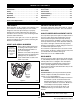
CONTROLS AND FEATURES 18 12 11 27 17 14 4 5 3 19 1 6 28 8 29 2 20 15 26 21 13 23 24 30 25 22 16 7 9 10 OS1132 OS0592 Figure 1 ENGLISH 1. Traction Drive Clutch Lever 2. Attachment Clutch Lever 3. Ignition Key (119, 120) 4. Primer Bulb 5. Choke 6. Throttle 7. Speed Selector 8. Recoil Starter Handle 9. Deflector Remote Control (119, 502, 503) 10. Chute Crank (119, 120, 333, 334) 11. Discharge Chute Deflector 12. Discharge Chute 13. Auger 14. Impeller 15. Scraper Blade 16. Runner 17.
ESPAÑOL 1. Palanca del embrague de la transmisión de la tracción 2. Palanca del embrague del accesorio 3. Llave de encendido (119, 120) 4. Botón del cebador 5. Estrangulador 6. Aceleración 7. Selector de velocidad 8. Manilla de retroceso del motor de arranque 9. Control remoto del deflector (119, 502, 503) 10. Manivela de la tolva (119, 120, 333, 334) 11. Deflector de la tolva de descarga 12. Tolva de descarga 13. Sinfín 14. Propulsor 15. Cuchilla raspadora 16. Guía 17. Luces delanteras 18.
TABLE OF CONTENTS Controls and Features . . . . . . . . . . . . . . . . . . . . . . 3 Storage . . . . . . . . . . . . . . . . . . . . . . . . . . . . . . . . . 20 Introduction . . . . . . . . . . . . . . . . . . . . . . . . . . . . . . 5 Accessories . . . . . . . . . . . . . . . . . . . . . . . . . . . . . 21 Safety . . . . . . . . . . . . . . . . . . . . . . . . . . . . . . . . . . . 6 Service Parts . . . . . . . . . . . . . . . . . . . . . . . . . . . . 21 Assembly . . . . . . . . . . . . . . . . .
2. Understand all Safety Precautions provided in the manuals. 3. Review control functions and operation of the unit. Do not operate the Sno-Thro unless all controls function as described in this manual. 4. Review recommended lubrication, maintenance and adjustments. 5. Review Limited Warranty Policy. Fill out Original Purchaser Registration Card and return the card to Ariens Company. SAFETY SAFETY ALERTS SAFETY DECALS AND LOCATIONS Look for these symbols to point out important safety precautions.
3. DANGER! Rotating parts! Stop engine and remove key before clearing. High speed impeller rotates below discharge opening. Wait for all moving parts to stop before removing clogs or servicing. 4. HOT SURFACES! DO NOT touch parts which are hot from operation. ALWAYS allow parts to cool. ASSEMBLY SAFETY RULES Read, understand, and follow all safety practices in Owner/Operator Manual before beginning assembly. Failure to follow instructions could result in personal injury and/or damage to unit.
DO NOT operate at too fast a rate. Slow down and turn corners slowly. Do not operate in reverse unless absolutely necessary. ALWAYS back up slowly. Always look down and behind before and while backing. Disengage attachment drive when traveling from one work area to another. Abnormal Vibrations are a warning of trouble. Striking a foreign object can damage unit. Immediately stop unit and engine. Remove key and wait for all moving parts to stop. Remove wire from spark plug.
Fumes from engine exhaust can cause injury or death. DO NOT run engine in an enclosed area. Always provide good ventilation. ALWAYS maintain unit in safe operating condition. Damaged or worn out muffler can cause fire or explosion. Keep all hardware properly tightened. Check shear bolts frequently. STORAGE SAFETY RULES NEVER store unit with fuel in fuel tank, inside a building where any ignition sources are present. Allow engine to cool completely before storing in closed area or covering unit.
Deflector Remote (502,503,119) 7. Install wing nut and bolt removed in step 2 onto shift rod and tighten hardware. 1. Slide cable end through hole on bracket on left side of chute. 2. Attach cable eye to stud on deflector. Hold in place with flat washer and e-ring. 3. Check deflector travel. Adjust nut on cable end under handlebar to obtain full travel. Install Discharge Chute and Crank (119,120,333,334) 1. Grease discharge chute ring on blower housing (if not already greased). 2.
Check Function of all Controls Ensure unit runs and performs properly. Refer to Operation. OPERATION Ignition Key (12V start on dash panel) WARNING: AVOID INJURY. Read and understand Operational, Fuel and Battery Safety Rules before proceeding. 1 2 3 STANDARD CONTROLS OS0232 See Figure on page 3 for all Controls and Features locations. Primer Bulb Pushing the Primer Bulb in adds fuel for easier engine start (see Starting and Shut Off).
Electric Starter Differential Lock (120,333,334,502,503) The Electric Starter will start a properly choked and cranked engine when the key is turned (12V) or start button (120V) is pushed. Refer to Starting and Shut-Off. Differential Lock knob is located on the Left Wheel Hub. With differential locked power is applied equally to both wheels. To engage differential lock: 2 • Pull and turn knob to LOCKED (1) position and release (knob will snap in OL2730 place when positioned correctly).
IMPORTANT: DO NOT use gasohol or gasoline containing alcohol. See Engine Manual for correct type and grade of fuel. 5. Fill fuel tank to within 1/2" (1,2 cm) below bottom of filler neck with unleaded gasoline. Tank capacity is 1 gallon (3,8 liters). 6. Replace Fuel Cap and tighten. 7. ALWAYS clean up any spilled fuel. PRE-START Frozen Impeller IMPORTANT: Before engine start check Impeller to be sure it is not frozen.
IMPORTANT: DO NOT operate starter more than 15 seconds per minute, as overheating and damage can occur. (If engine does not start, refer to Troubleshooting.) 9. Adjust choke as needed. 10. Disconnect power cord from receptacle. 11. Set throttle to “Part Throttle” or “Slow” position for adaptation to Ambient temperature or transport. Once achieved, set throttle to “Fast” position for normal operation. Electric Start (12V) 1. Turn discharge chute straight ahead. 2.
MAINTENANCE Ariens Dealers will provide any service or adjustments which may be required to keep your unit operating at peak efficiency. Should engine service be required, contact an Ariens dealer or an authorized engine manufacturer's service center. WARNING: AVOID INJURY. Read and understand Maintenance and Service and Battery Safety Rules in Safety section before attempting any maintenance. Change oil after first 5 hours of operation, thereafter change oil every 25 hours (more often if required).
GENERAL LUBRICATION CLEAN BATTERY (Model 333,334,502,503) Sno-Thro should be lubricated (Figure 9) at beginning of season or every 25 operating hours. IMPORTANT: DO NOT allow grease or oil to get on friction wheel, drive disc or belts. IMPORTANT: Wipe each fitting clean before and after lubrication. NOTE: Apply Stens Mix Hi-Temp Grease or equivalent to the lubrication fittings. See Service Parts. Auger Shaft NOTE: To grease auger shaft, remove shear bolt nuts, and shear bolts.
SERVICE AND ADJUSTMENTS 2. With runners adjusted to their full up position, reposition scraper blade down, flush with runners, and tighten lock nuts. WARNING: AVOID INJURY. Read and understand Maintenance and Service and Battery Safety Rules in Safety section before attempting any maintenance. DISCHARGE CHUTE If Chute does not stay in position while operating, tighten nut on carriage bolt at pivot point to increase tension on spring (Figure 11).
4. Measure distance between impeller brake shoe pad and belt with attachment clutch engaged (Figure 13). Impeller brake shoe should be 1/16" (1,6 mm) minimum from belt. When attachment clutch is disengaged, brake must contact belt. If brake travel does not meet these requirements, contact your Dealer. 3 5 3/8" (9mm) DRIVE CHAIN Chain should be taut with little or no play in it. To compensate for looseness or excessive tightness in drive chain. 1. Put unit into service position. 2.
10. Place belt onto engine sheave. 11. Make sure engine and attachment sheaves align. If alignment is necessary, loosen attachment sheave set screws, reposition sheave and retighten set screws. 12. Reposition and secure belt fingers. IMPORTANT: Make sure belt fingers are 1/16" to 1/8" (2-3mm) from belt when attachment clutch is engaged. 1 3 2 5 4 6 13. Check adjustment. See Attachment Clutch/Brake.
Replacing 3. Secure Shear Bolt with nut. Use U1R or U1L; 340 to 350 CCA @ 0˚F type batteries. FRICTION WHEEL 1. Place unit into service position. 2. Remove bottom cover by removing four cap screws. 3. Place Speed Selector in first (1) position and depress Traction Clutch Lever to hold friction wheel and hub into position. 4. Remove cap screws (Figure 17). 5. Release traction clutch lever, shift to third (3) position, and remove friction wheel. 6.
. ACCESSORIES SERVICE PARTS See your authorized Ariens dealer to add the additional accessories available to your Sno-Thro. Part No. Description 71099700 Slicer Bar 72406400 Remote Deflector Control Order the following parts through your Dealer: Part No. Description 00036800 Stens Mix Hi-Temp Grease (3, 3 oz.
SPECIFICATIONS Model Number 924119 Description Engine Tecumseh 924120 924333 924334 924502 924503 1332 1336 1028 1024 1024 1128 HMSK100159468W OHSK100221608B OHSK100221609B OHSK110221716B OHSK130-223815C 11 (8.2) 13 (9.7) 10 (7.46) Power Max - HP (Kw/min-1) 3600 ± 150 Fast Idle Speed - RPM (min-1) Displacement - in (cc) 3500 ± 150 21.82 (357.6) Electric Start 19.43 (318.3) 21.82 (357.6) Yes, 120V Yes, 12V Fuel See Engine Manual Tank Capacity - qt (Liters) 4 (3.
2 Year Limited Warranty Ariens Company 655 West Ryan Street P.O. Box 157 Brillion, WI 54110-0157 920-756-2141 Fax 920-756-2407 www.ariens.
GB - 24
Ariens Company 655 West Ryan Street P.O. Box 157 Brillion, WI 54110-0157 920-756-2141 Fax 920-756-2407 www.ariens.