
Specifications

GB - 17
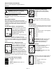
MANUAL DEFLECTOR (120,333,334)
To adjust, loosen then retighten hardware to desired
deflector drag force (Figure 5).
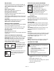
DEFLECTOR REMOTE (119,502,503)
Adjust nuts as required at end of cable just beneath
control panel (Figure 7).
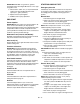
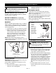
RUNNERS
Runners should be adjusted (Figure 10) as conditions
require. Raising or lowering runners controls distance
scraper blade (auger/impeller housing) is held above
surface being cleared.
1. Position unit on a hard, flat, smooth level surface.
2. Adjust runners by inserting a spacer of desired
thickness under center of scraper blade, loosen
runner hardware, slide runners to flat surface.
Allow 1/8" (3mm) between scraper blade and
hard smooth surfaces. Allow 1-1/4" (30mm)
between scraper blade and uneven surface(s).
Retighten hardware.
NOTE: Keep housing level by adjusting runners
equally. Uneven runners make unit difficult to steer and
results in uneven clearing.
SCRAPER BLADE
IMPORTANT: Damage to auger/impeller housing will
result if blade wears down too far.
Scraper blade is adjustable to compensate for wear.
To adjust scraper blade:
1. Tip unit back onto handlebar, support housing
and loosen nuts retaining blade.
2. With runners adjusted to their full up position,
reposition scraper blade down, flush with runners,
and tighten lock nuts.
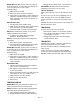
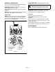
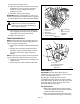
DISCHARGE CHUTE
If Chute does not stay in position while operating,
tighten nut on carriage bolt at pivot point to increase
tension on spring (Figure 11).
Smooth and easy rotation of properly lubricated chute
with crank is obtained by adjusting pinion and chute
gear teeth so they mesh together.
Adjust, using adjustment slots in pinion bracket which
is secured to chute strap.
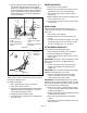
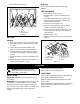
ATTACHMENT CLUTCH BRAKE
To properly adjust attachment clutch:
1. Remove belt cover. When clutch is disengaged
there should be a slight amount of slack in the
auger cable to allow for brake wear.
2. Clutch cable spring should extend approximately
3/8" (9,5 mm) when clutch is engaged but allow
clutch arm to return to it's maximum down
position when clutch is disengaged. To increase
spring extension, loosen adjustment hardware
(Figure 14) and move the idler toward the belt .
Approximately 1/8" (3,2 mm) movement of the
idler will increase spring extension by 1/8" (3,2
mm).
3. To check impeller brake, place unit in service
position. Remove bottom cover by removing four
cap screws.
SERVICE AND ADJUSTMENTS
WARNING: AVOID INJURY. Read and
understand Maintenance and Service and
Battery Safety Rules in Safety section before
attempting any maintenance.
1. Runner
2. Runner Hardware
2
1
Figure 10
OS0485
WARNING: AUGER / IMPELLER MUST
STOP within 5 seconds when Attachment
Clutch Lever is released or unit damage or
serious injury may result.
1. Carriage Bolt
2. Spring
3. Pinion
Bracket
4. Pinion
5. Chute Strap
6. Chute Gear
7. Gear Strap
8. Mounting Nut
9. Chute Ring
10. Lower Ring
11. Retainer Clip
3
1
6
7
8
2
4
5
11
10
9
Figure 11
DS0112