Sno-Thro ® Owner/Operator Manual Models 924124 – ST926DLE 924125 – ST11528LE 924126 – ST11526DLE 924127 – ST11528DLE 924128 – ST1332LE 924335 – ST926DLE 924336 – ST11526DLE 924337 – ST11528DLE 924338 – ST1332LE 924516 – ST1332DLE 924517 – ST1336DLE ENGLISH FRANÇAIS ESPAÑOL Transfer model & serial number label from product registration here. Coller l’autocollant du modèle et du numéro de série dans cet encadré. Transferir aquí la etiqueta del modelo y número de serie del registro del producto.
Ariens Company 655 West Ryan Street P.O.
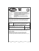
Representative Measured Sound Power Level (Lwa) – Niveau de puissance acoustique représentatif mesuré (Lwa) – Repräsentativer gemessener Geräuschpegel (Lwa) – Livello di potenza sonora rappresentativo rilevato (Lwa) – Nivel de potencia acústica representativo medido (Lwa) – Representativt målt lydeffektnivå (Lwa) – Representativ uppmätt ljudnivå (Lwa) – Tyypillinen mitattu äänitehotaso (Lwa) – Zmierzony reprezentatywny poziom mocy akustycznej (Lwa) – Guaranteed Sound Power Level (Lwa) – Niveau de puissance
TABLE OF CONTENTS Safety . . . . . . . . . . . . . . . . . . . . . . . . . . . . . . . . 5 Storage . . . . . . . . . . . . . . . . . . . . . . . . . . . . 27 Assembly . . . . . . . . . . . . . . . . . . . . . . . . . . . 9 Service Parts . . . . . . . . . . . . . . . . . . . . . . . 27 Controls and Features . . . . . . . . . . . . . . . 13 Accessories . . . . . . . . . . . . . . . . . . . . . . . . 27 Operation . . . . . . . . . . . . . . . . . . . . . . . . . . 14 Troubleshooting . . . . . . . . . .
DELIVERY Customer Note: If you have purchased this product without complete assembly and instruction by your retailer, it is your responsibility to: 1. Read and understand all assembly instructions in this manual. If you do not understand or have difficulty following the instructions, contact your nearest Ariens Dealer for assistance. Make sure all assembly has been properly completed. NOTE: To locate your nearest Ariens Dealer, call 1-920-756-4664 or go to www.ariens.com on the internet.
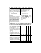
SAFETY DECALS AND LOCATIONS ALWAYS replace missing or damaged Safety Decals. Refer to figure below for Safety Decal locations. Never direct discharge towards persons or property that may be injured or damaged by thrown objects. OL0910 Stop engine, remove key, read manual before making any repairs, adjustments. 3 2 Wear appropriate hearing protection. ONLY use clean-out tool to clear blockages. NEVER use your hands. 3. DANGER! 1 Figure 2 OS6600 1. DANGER! OS2080 ROTATING PARTS.
Keep area of operation clear of all toys, pets, and debris. Thrown objects can cause injury. Deflected materials can cause injury and property damage. Check for weak spots on docks, ramps or floors. Avoid uneven work areas and rough terrain. Stay alert for hidden hazards. Always stand clear of the discharge area when operating this unit. Fumes from engine exhaust can cause injury or death. DO NOT run engine in an enclosed area. Always provide good ventilation. Avoid uneven and rough terrain.
Before cleaning, removing clogs or making any inspections, repairs, etc.: disengage clutch(es), stop unit and engine, remove key, allow moving parts to stop. Allow hot parts to cool. Run unit a few minutes after clearing snow to prevent freeze-up of attachment. Disengage attachment when not in use. Disengage all clutches before starting engine. Adjust runners to clear gravel or crushed rock surfaces safely. Never leave a running unit unattended. ALWAYS shut off engine before leaving unit.
• In case of internal contact, DO NOT induce vomiting! Before tipping unit up onto housing, remove fuel so no spills will occur and remove battery. Ensure unit is secure and will not tip over during maintenance. ALWAYS keep protective structures, guards, and panels in good repair, in place and securely fastened. NEVER modify or remove safety devices. Keep all hardware properly tightened. Check shear bolts frequently. Maintain or replace safety and instruction labels, as necessary.
4 2 1 2 6 2 3 4 1 5 1 1. Mounting Hardware 2. Discharge Chute 3 1. Handlebar Assembly 2. Wing Knobs 3. Wing Nut 3. Chute Pedestal 4. Discharge Chute Ring Figure 5 4. Speed Selector 5. Bolt 6. Shift Rod OS6610 OS6620 1 Figure 4 OS3020 Install Discharge Chute (924124-128, 335-338, 516) Figure 5. 1. Grease underside of discharge chute ring (if not already greased). 2. Remove mounting hardware from auger housing. 3.
2. Turn the chute gear until the solid pin is towards the rear of the unit and a threaded stud aligns with the chute motor (Figure 7). 3. Remove the six (6) nuts and two half rings (Figure 7). 4. Make sure the three (3) chute clamps on the chute gear are underneath the discharge chute flange as shown in (Figure 8) 5. Install discharge chute on blower housing with the opening of the discharge chute facing towards the front of the unit (Figure 9). 6. Install two (2) half rings on unit with six (6) nuts.
Connect Battery (924516, 517) 1. Remove wing nuts from battery cover. 2. Install wire lead to battery terminal. 3. Install battery cover and tighten wing nuts. Deflector Remote 1. Remove e-ring and flat washer from stud on discharge chute. 2. Route deflector remote cable between the engine and the chute pedestal. 3. Slide cable end through hole on bracket on left side of chute (Figure 10). 4. Attach cable eye to stud on deflector. Hold in place with flat washer and e-ring. 5. Check deflector travel.
CONTROLS AND FEATURES 1 37 2 4 5 6 3 7 36 35 34 33 8 9 32 31 10 30 11 29 28 12 27 13 14 15 16 17 1 18 26 19 25 24 23 22 20 21 Figure 11 19 1. Traction Drive Clutch Lever 2. Oil Fill/Dipstick 3. Muffler Guard 4. Belt Cover 5. Discharge Chute Deflector 6. Discharge Chute 7. Electric Chute Motor 8. Impeller 9. Clean-out Tool 10. Auger Gearcase 11. Scraper Blade 12. Auger 13. Recoil Starter Handle 14. Primer Bulb 15. Choke Control Knob 16. Throttle (Engine Stop) 17. Oil Drain Plug 18.
OPERATION IMPORTANT: If the belt squeals when the attachment clutch lever is engaged, the attachment drive may be frozen. Immediately release the attachment clutch lever and move the unit into a heated area to thaw. WARNING: AVOID INJURY. Read and understand the entire Safety section before proceeding. WARNING: To avoid injury to hands and feet, always disengage clutches, shut off engine, and wait for all movement to stop before unclogging or working on snow thrower.
Choke Control Knob 2 1 OS1332 1. Choke Closed position: chokes off air to engine for easier start. 2. Choke Open position: allows for normal operation. IMPORTANT: Gradually open choke after engine starts. Throttle 1 2 3 STOP The throttle controls the engine speed. To increase or decrease the engine speed, adjust to: 1. Fast (normal or warm starts) 2. Part-Throttle 3. Slow (cold weather starts) 4.
Differential Lock (924124, 126, 127, 335, 336, 337, 516, 517) 1 2 OL2730 Scraper Blade Differential Lock knob is located on the Left Wheel Hub. With differential locked power is applied equally to both wheels. To engage differential lock: • Pull and turn knob to LOCKED (1) position and release (knob will snap in place when positioned correctly). To resume differential action for transport: • Pull and turn knob to UNLOCKED (2) position and release.
FILLING FUEL TANK 3. Differential Lock (924124, 126, 127, 335, 336, 337, 516, 517) WARNING: AVOID INJURY. Read and understand the entire Safety section before proceeding. ALWAYS engage differential lock (located in left wheel hub) for best traction when throwing snow. Fuel Shut-Off Valve 4. Adjust Axle Lock (924125, 128, 338) IMPORTANT: The fuel shut-off valve MUST be in the closed position prior to transporting the unit.
NOTE: When temperature is below -15° F (-26° C) additional priming may be needed. 4. If engine is cold, apply choke. See Engine Manual for detailed instructions. NOTE: A warm engine requires less choking than a cold engine. 5. Set throttle to proper starting position. 6. Insert key into ignition switch. 12V - Turn key into RUN position. 120V or 240V - Push key into RUN position. DO NOT twist key after it is inserted. 7. Grasp starter handle and pull rope out slowly until it pulls harder.
TRAVELING 1. Select Speed Control position and direction. 2. Engage Attachment Clutch - Right Hand Lever. 3. Engage Traction Drive Clutch - Left Hand Lever. IMPORTANT: DO NOT overload unit capacity by attempting to clear snow at too fast a rate. Use slow speed to clear deep or hard packed snow. To travel from one work area to another: 1. Set Throttle to Slow or Part-Throttle position. 2. Press down on handlebars enough to raise front of unit slightly off surface. 3.
CHECK DUAL HANDLE INTERLOCK Without the engine running, press down (engage) both clutch levers. Release attachment clutch lever. Attachment clutch should remain engaged until traction clutch lever is released, then both clutches must disengage. CHECK FASTENERS Make sure all hardware is tightened properly. CHECK CLUTCHES Auger / impeller must stop within 5 seconds when attachment clutch/impeller brake lever is released. Wheels must stop quickly when traction drive clutch lever is released.
2 8 6 5 4 1 1 1 1 7 3 1. Auger and Shaft 2. Discharge Chute 3. Sprocket/Pinion Assembly 4. Axle Shaft 5. Shift Lever Arm 6. Pinion Chain 7. Hex Shaft 8. Shift Link Grease Oil OS0642 OS0741 Figure 15 Terminals CLEAN BATTERY (924516, 517) WARNING: AVOID INJURY. Read and understand the entire Safety section before proceeding. IMPORTANT: Battery is maintenance free. Do not tamper with or attempt to open battery. See Service and Adjustments for charging procedures.
1 2 1, 2 OS0001 4 3 1, 2 1. Carriage Bolt 2. Spring OS6700 1. Nut 2. Pressure Flange 3. Adjusting Nuts 4. Cable Support Bracket DS6730 Figure 17 RUNNERS Figure 16 DISCHARGE CHUTE If chute does not stay in position while operating, tighten nut on carriage bolt at pivot point to increase tension on spring (Figure 17). Runners should be adjusted (Figure 18) as conditions require. 1. Position unit on a hard, flat, smooth level surface. 2.
For Replacement: 1. Align shear bolt holes in auger with shear bolt holes in the shaft. 2. Drive shear bolt through hole (if shear bolt was broken this will drive remaining part from shaft). 3. Secure shear bolt with nut. 2 SPEED SELECTOR ADJUSTMENT 1 1. Runner 2. Runner Hardware Figure 18 SCRAPER BLADE IMPORTANT: Damage to auger/impeller housing will result if blade wears down too far. Scraper blade is adjustable to compensate for wear. To adjust scraper blade: 1.
ATTACHMENT CLUTCH/BRAKE ADJUSTMENT a.Loosen the idler adjustment nut. (Figures 21 and 22) IMPORTANT: IMPROPER ADJUSTMENT could result in unexpected movement of auger and impeller causing death or serious injury. Auger / impeller must stop within 5 seconds when Attachment Clutch/Impeller Brake lever is released. 1. Remove belt cover. 2. Check belt alignment (Figure 24). Engine sheave and attachment pulley must align vertically. Also, belt must be centered in the idler pulley.
ATTACHMENT DRIVE BELT REPLACEMENT Remove old attachment drive belt: 1 2 OS0660 Minimum of 1/16 in. (1.6 mm) 1. Drive Belt 2. Brake Shoe and Pad Figure 22 TRACTION DRIVE CLUTCH ADJUSTMENT If drive slips, adjust traction clutch to compensate for friction disc wear. To adjust traction clutch: 1. Place speed selector in First (1) Forward. 2. Place unit in service position. 3.
6 4 7 3 2 8 1 1. Traction Belt Idler 2. Cap Screw 3. Belt Finger 4. Traction Drive Belt 5. Attachment Belt Idler 6. Attachment Drive Belt 7. Engine Sheave 8. Attachment Pulley 9. Attachment Idler Adjustment Nut 5 9 Figure 24 8. Remove attachment drive belt from attachment pulley (hold brake away from belt). Install new attachment drive belt: 1. Place new attachment belt onto attachment pulley. 2. Tip housing and frame back together and secure with cap screws. 3. Place belt onto engine sheave. 4.
SHORT TERM 5. Release traction clutch lever, shift to third (3) position, and remove friction disc. 6. Secure new friction disc on hub with five cap screws and torque cap screws to 8-10 lbf-ft (10,6-13,3 N•m). 7. Replace bottom cover. 8. Adjust traction drive clutch (see Traction Drive Clutch Adjustment). 1 2 IMPORTANT: NEVER spray unit with high pressure water or store unit outdoors. Run with attachment clutch engaged a few minutes after each use to free unit of any loose or melting snow.
* Available in CE countries. TROUBLESHOOTING PROBLEM Engine will not crank/start. Engine stops. PROBABLE CAUSE CORRECTION 1. Fuel tank is empty. 2. Fuel shut-off valve closed. 3. Build up of dirt and residue around governor/carburetor. 4. Key Switch not in run position. 5. Ignition switch starter circuit not functioning. 6. Battery discharged, wires loose. 1. Fill fuel tank. 2. Open fuel shut-off valve. 3. Clean area around governor/carburetor. 1. Out of fuel. 2. Fuel shut-off valve closed. 1.
SPECIFICATIONS Model Number Description Engine - Tecumseh Power Max - HP (kW) Fast Idle Speed - RPM (min-1) Displacement in. (cc) Electric Start Fuel Tank Capacity qt (Liters) Snow Clearing Width - in. (cm) Chute Rotation Angle Rotation Control at Handlebar Remote Deflector Control Impeller Diameter - in. (cm) 924124 ST926DLE OH318SA 9.0 (6.71) 924125 924126 924127 924128 ST11528LE ST11526DLE ST11528DLE ST1332LE OH318SA OH358SA 11.5 (8.6) 13.0 (9.7) 3600 ± 150 19.43 (318.3) 120V See Engine Manual 4 (3.
SPECIFICATIONS Model Number 924335 924336 924337 924338 924516 924517 Description ST926DLE ST11526DLE ST11528DLE ST1332LE ST1332DLE ST1336DLE Engine - Tecumseh OH318SA OH318SA OH358SA OH358SA Power Max - HP (kW) 9.0 (6.71) 11.5 (8.6) 13.0 (9.7) Fast Idle Speed - RPM 3600 ± 150 (min-1) Displacement 19.43 21.82 in. (cc) (318.3) (357.6) Electric Start 240V 12V Fuel See Engine Manual Tank Capacity 4 (3.8) qt (Liters) Snow Clearing Width - in. 26 (66.0) 28 (71.2) 32 (81.3) 36 (91.
3-Year Limited Sno-Thro Warranty Ariens Company 655 West Ryan Street P.O. Box 157 Brillion, WI 54110-0157 920-756-2141 Fax 920-756-2407 www.ariens.
Ariens Company 655 West Ryan Street P.O. Box 157 Brillion, WI 54110-0157 920-756-2141 Fax 920-756-2407 www.ariens.