Sierra ® Service Manual Models 936014-026, 936305-313 03675400 04/00 Printed in USA
SECTION - INTRODUCTION TABLE1OF CONTENTS Section 1 - Introduction . . . . . . . . . . . . . . . . . . 1.1 The Manual . . . . . . . . . . . . . . . . . . . . . . . . 1.2 Service and Replacement Parts . . . . . . . . 1.3 Product Registration . . . . . . . . . . . . . . . . . 1.4 Unauthorized Replacement Parts . . . . . . . 1.5 Disclaimer . . . . . . . . . . . . . . . . . . . . . . . . . 1.6 Technical Service Communications . . . . . . 1.7 Preparation . . . . . . . . . . . . . . . . . . . . . . . .
SECTION 1 - INTRODUCTION 1.1 THE MANUAL 1.3 PRODUCT REGISTRATION The purpose of this manual is to provide complete instructions for service, maintenance, disassembly, repair, and installation of the mechanical components for the unit. A warranty registration card must be filled out, signed, and returned at time of purchase. This card activates the warranty. Claims meeting requirements during limited warranty period will be honored.
1.7 PREPARATION Before starting any removal of parts, proper preparation is very important for efficient work. A clean work area at the start of each job will allow you to perform service repairs easily and quickly. in the disassembly order on a clean work surface. Organization is a key part of proper reassembly. Tools, instruments, and parts needed for the job should be gathered before work is started. Interrupting a job to locate tools or parts is a needless delay.
Disengage mower clutch, stop engine, remove key and wait for moving parts to stop before leaving operators position for any reason such as removing grass catcher or unclogging chute. Mow only in daylight or good artificial light. Do not operate the machine while under the influence of medication, alcohol or drugs. Do Not Do not turn on slopes unless necessary, and then, turn slowly and gradually, downhill, if possible. Do not mow near drop-offs, ditches, or embankments.
Keep machine free of grass, leaves, or other debris build-up. Clean up oil or fuel spillage. Allow machine to cool before storing. Stop and inspect the equipment if you strike an object. Repair any damage before restarting. Never make adjustments or repairs with the engine running or when engine and exhaust parts are hot from operation. Grass catcher components are subject to wear, damage, and deterioration, which could expose moving parts or allow objects to be thrown.
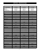
SECTION 3 - SPECIFICATIONS Model No. 936014 936015 936016 Description Name Sierra 1340G Sierra 1440G Sierra 1340H 66.50 (1.68) 41.25 (1.05) 52.00 (1.32) 46.00 (1.17) 480 (217) 66.50 (1.68) 41.25 (1.05) 52.00 (1.32) 46.00 (1.17) 480 (217) 66.50 (1.68) 41.25 (1.05) 52.00 (1.32) 46.00 (1.17) 480 (217) Length, in. (m) Height, in. (m) Width, in. (m) Wheel Base, in. (m) Actual Weight, lbs.
Model No. 936017 936018 936019 Description Name Sierra 1440H Sierra 1540H Sierra 1640H 66.50 (1.68) 41.25 (1.05) 52.00 (1.32) 46.00 (1.17) 480 (217) 66.50 (1.68) 42.00 (1.07) 52.00 (1.32) 46.00 (1.17) 480 (217) 66.50 (1.68) 42.00 (1.07) 52.00 (1.32) 46.00 (1.17) 480 (217) Length, in. (m) Height, in. (m) Width, in. (m) Wheel Base, in. (m) Actual Weight, lbs.
Model No. 936020 936021 936022 Description Name Sierra 1640H Sierra 1648H Sierra 1340G 66.50 (1.68) 42.00 (1.07) 52.00 (1.32) 46.00 (1.17) 480 (217) 66.50 (1.68) 42.00 (1.07) 52.00 (1.32) 46.00 (1.17) 518 (234) 66.50 (1.68) 41.50 (1.06) 52.00 (1.32) 46.00 (1.17) 480 (217) Length, in. (m) Height, in. (m) Width, in. (m) Wheel Base, in. (m) Actual Weight, lbs.
Model No. 936023 936024 936025 Description Name Sierra 1540H Sierra 1548H Sierra 1640H 66.50 (1.68) 42.00 (1.07) 52.00 (1.32) 46.00 (1.17) 480 (217) 66.50 (1.68) 42.00 (1.07) 52.00 (1.32) 46.00 (1.17) 518 (234) 66.50 (1.68) 41.50 (1.06) 52.00 (1.32) 46.00 (1.17) 518 (234) Length, in. (m) Height, in. (m) Width, in. (m) Wheel Base, in. (m) Actual Weight, lbs.
Model No. 936026 936305 936306 Description Name Sierra 1540H Sierra 1640G Sierra 1640H 66.50 (1.68) 66.50 (1.68) 66.50 (1.68) 42.50 (1.08) 42.50 (1.08) 41.25 (1.05) 52.00 (1.32) 52.00 (1.32) 52.00 (1.32) 46.00 (1.17) 46.00 (1.17) 46.00 (1.17) 480 (217) 400 (181) 480 (217) 12 Volt 290 CCA 12 Volt 290 CCA 12 Volt 290 CCA Optional (736008) Optional (736008) Optional (736008) Seat High Medium Medium Brakes Disc. Disc. Disc.
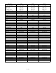
Model No. 936307 936308 936309 Description Name Sierra 1640H Sierra 1640G Sierra 1648H 66.50 (1.68) 42.00 (1.07) 52.00 (1.32) 46.00 (1.17) 480 (217) 66.50 (1.68) 41.25 (1.05) 52.00 (1.32) 46.00 (1.17) 480 (217) 66.50 (1.68) 42.00 (1.07) 52.00 (1.32) 46.00 (1.17) 518 (234) Length, in. (m) Height, in. (m) Width, in. (m) Wheel Base, in. (m) Actual Weight, lbs.
Model No. 936310 936311 936312 Description Name Sierra 1648H Sierra 1640H Sierra 1540G 66.50 (1.68) 42.00 (1.07) 52.00 (1.32) 46.00 (1.17) 480 (217) 66.50 (1.68) 41.25 (1.05) 52.00 (1.32) 46.00 (1.17) 480 (217) 66.50 (1.68) 42.00 (1.07) 52.00 (1.32) 46.00 (1.17) 480 (217) Length, in. (m) Height, in. (m) Width, in. (m) Wheel Base, in. (m) Actual Weight, lbs.
Model No. 936313 Description Name Sierra 1648H Length, in. (m) Height, in. (m) Width, in. (m) Wheel Base, in. (m) Actual Weight, lbs. (kg) Battery 66.50 (1.68) 42.00 (1.07) 52.00 (1.32) 46.00 (1.17) 518 (234) 12 Volt 290 CCA Hour Meter Optional (736008) Seat High Brakes Disc. Steering Gear Turning Radius, in. (cm) 26 (66) Tire Size Front 15x6.00-6 Rear 20x8.00-8 Diagnostic Lights Engine Yes OHV 16 HP Manufacture Briggs & Stratton Fuel and Capacity, gal. (L) Unleaded, 3 (11.
SECTION 4 - GENERAL MAINTENANCE & ADJUSTMENTS 4.1 CONTROLS AND FEATURES 3 1 14 13 6 077180 OT0200 12 11 21 1. Fuel Tank Fill 2. Clutch/Brake Pedal 3. Attachment Lift Lever 4. Throttle/Choke Lever 5. Head Light Switch 6. Travel Speed Selector (Gear only) 7. Ignition/Key Switch 8. PTO Switch 9. Headlights 10.Parking Brake control 11.Fuel Level Indicator 12.Seat Position or Adjustment 13.Transmission Disconnect Control (Hydro Only) 14.Expansion Hose with Vent (Hydro Only) 15.Mower Height Indicator 16.
4.2 FILLING THE FUEL TANK WARNING: Use caution with fuel. Fuel is very flammable. Keep fuel in a clean and tight container. Keep fuel away from fire and heat. Never put fuel in the fuel tank while the engine is running or hot. Clean up any spilled fuel before starting the engine. Add fuel to the fuel tank as needed. See your engine manual for the correct type and grade of fuel to be used. 1. Put the unit in an open and well ventilated area prior to refueling. 2. Stop the engine and set the parking brake.
4. Put the dipstick back into the engine, tighten in place, and remove again. 5. When the dipstick is removed, note the oil level and add oil accordingly. Do not over fill. 4.6 CHANGING OIL WARNING: Engine muffler and other parts will be hot if unit has been running. Engine oil should be changed after the first 5 hours of operation and every 25 hours there after. 1. Move the unit to a level and well ventilated area and set the parking brake. 2. If the engine is cold, let the unit run for 5 minutes.
4.11 CHECKING THE TRANSMISSION FLUID (HYDRO) The transaxle is filled and tested at the factory and should not require fluid when the unit is put into service. Inspect the transaxle for leaks or damage to the housing. If leakage is observed, do not operate until the leakage is repaired. Check the oil level and fill to the correct level if needed. Figure 10 936-8 3. Start engine and run at low idle. 4. Stroke the travel control pedal forward for five seconds and then reverse for five seconds.
2 3 1 Figure 12 936-8 1. Neutral Adjustment Bolt 2. Spring-Forward 3. Spring-Reverse 5. If meter reads below 6.00 ohms or above 8.00 ohms, then the clutch has failed and needs to be replaced. Figure 13 6. If meter reads between 6.00 to 8.00 ohms, proceed to measure clutch current draw. OT0041 4. Turn the adjustment bolt counterclockwise until the wheels turn in the other direction. Measure Clutch Current Draw 1. Turn engine off. 5. Center the adjustment bolt between these two points. 2.
6. Adjust the ball joint to align with ball on the transaxle shift arm. Attach the ball joint to the ball on the shift arm. 4.16 ADJUSTMENT OF DIRECTIONAL CONTROL PEDAL Remove the clevis pin holding the shift rod to the control pedal cross shaft. Push the forward pedal down and mark the pedal arm. Depress the rear directional control pedal and mark the pedal arm. Place the pedal arm in the center of the forward and reverse marks and adjust the clevis to allow the clevis pin to be installed.
tension spring is 4.5" or shorter the belt is worn and will need to be replaced. 3 4 1 2 1. Disc Brake 2. Adjustment Nut 3. Compression Spring .78" x 1" long Figure 18 Figure 20 936-15 OT0830 With the parking brake set, the rear compression spring on the brake arm should be compressed to 0.75" long. 4.21 MOWER BELT REPLACEMENT Disconnect the main idler spring from the unit frame and remove the PTO drive belt from the PTO clutch and the top of the mower deck jackshaft assembly.
4.23 TRANSAXLE BELT REPLACEMENT 1. Disconnect the main idler spring from the unit frame and remove the PTO drive belt from the PTO clutch and the top of the mower deck jackshaft assembly. 1 3 2 2 1 Figure 22 1. Tie Rod End 2. Jam Nut 3. Tie Rod 936-17 2. Remove the wire harness from the PTO clutch. Figure 23 3. Remove the cap screw, holding the step in the center of the PTO clutch and remove the strap from the clutch. 4. Loosen the hardware securing the belt finger to the main drive belt idler. 5.
SECTION 5 - ENGINE 5.1 ENGINE TROUBLESHOOTING The following trouble shooting chart is to be used to isolate engine problems and give possible causes and corrective action responses. TROUBLE The trouble shooting key is generic and can be used for several types of engines. Use only those possible causes and corrective actions that apply to the unit.
5.2 ENGINE REMOVAL 5.3 ENGINE INSTALLATION 1. Open and remove the hood from the unit. 1. Check the engine base and unit frame for damage before installing the engine. 2. Remove the negative cable from the battery. 2. Place the throttle, choke control, and electrical wire out of the way prior to placing the engine onto the unit frame. 3. Remove the attachment from the unit. 4. Remove the PTO clutch from the bottom of the engine sheave.
SECTION 6 - HYDRO DRIVE TRAIN 6.1 HYDRO TRANSMISSION TROUBLESHOOTING The following troubleshooting chart is to be used to isolate hydro transmission problems and give possible causes and corrective action responses.
6.2 FLUIDS/GREASES The fluids used in Hydro-gear transaxles have been carefully selected. If substitutions are made, use equivalent products. Typically, an engine oil with a minimum rating of 55 sus at 210oF (99oC) and an API classification of SH/CD is recommended. A 20W-50 engine oil has been selected for use by the factory. The grease used in the manufacture of Hydro-Gear products is a STEMS Premium grease and should be substituted with equivalent products only if it is not readily available in your area.
major disassembly of the unit. Replacement of these seals will require removal of the transaxle from the machine frame. 1. To remove the input shaft seal carefully pull the seal out of the housing bore with a "hook" type tool or a slide hammer type puller. Care must be taken to avoid damage to the housing bore or to the shaft sealing surface. Figure 27 18.Move the transaxle assembly to the rear and out of the unit frame. 19.
6.5 HYDRO TRANSMISSION REPAIR (MAJOR) CAUTION: The axle/differential assembly may stick as the lower housing is being lifted off of the upper housing. 1. Drain the oil by removing the breather assembly and positioning the transmission so the breather port is down to allow the oil to drain thoroughly. Figure 30 936-37 Figure 32 2. Position and secure the transmission with the upper housing down to allow access to the twenty housing assembly cap screws. 3.
Figure 33 936-23 Figure 34 12.Inspect the differential bevel gears by rotating the axle ends. 13.Inspect the final drive gear teeth for excessive wear or damage. 14.Check the differential assembly screw for proper torque. The correct torque should be 12-14 ft. lbs. (.75-.9 Nm). 15.Inspect the journal bearings inside the differential housing for excessive wear by feeling the shafts for an unreasonable amount of play. 936-29 24.Remove the center section assembly from the housing.
NOTE: The correct bore diameter for the block is 0.6776" to 0.6784" and the pistons should be 0.6767" to 0.6770". taken to avoid damage to the housing bore, shaft sealing surface or bearing. Once removed, the seal is not reusable. 26.Remove the motor shaft, washers and bypass plate from the center section and inspect for unusual wear or damage. 38.Remove the input shaft bearing ring. 27.Inspect the center section running surfaces for unusual wear or damage. 40.
Figure 37 936-32 Figure 38 11.Install the swashplate assembly into the housing. The slot on the swashplate must engage the slot guide block on the displacement control shaft. Use a tool such as a screwdriver to hold the guide block in position while installing the swashplate. 12.Install the thrust washer and pump block spring onto the pump shaft. 936-33 21.
than 10 PSI to be applied or seal damage may occur. To locate a leak, apply a soap mixture around the housing seam and at all lip seals. Do not submerge unit or the brake will be damaged. 26.Install the differential axle assembly into the housing. 27.Install a new filter onto the center section check valve plate. 28.Install the rotors and stators. Install a stator, then a rotor (hub to inside), then a stator, then a rotor (hub to inside), then two stators. Oil Fill & Start-Up Procedures 29.
6.6 HYDRO TRANSMISSION INSTALLATION 8. Check the belt fingers and belt alignment. Before installing the transaxle assembly into the unit frame with the axle subassembly installed the following items will need to be completed. 10.Reinstall the fuel tank and attach the fuel line, route the seat switch wires over the fuel tank. 6 2 3 9. Reinstall the rear tail board on the unit installing the dump valve rod and transaxle oil expansion hose.
SECTION 7 - GEAR DRIVE TRAIN 7.1 GEAR TRANSMISSION TROUBLESHOOTING The following troubleshooting chart is to be used to isolate hydro transmission problems and give possible causes and corrective action responses.
7.2 GEAR TRANSAXLE REMOVAL (PEERLESS) 8. Remove the oil from the unit prior to removing the gear shaft assemblies. 9. Remove the top bearing block on the bull gear of the differential. Remove the bull gear, bevel pinion gears with center shaft and the axles. 1. Place the unit on a flat surface and remove the negative lead from the battery and remove the spark plug lead from the spark plug. 2. Raise and support the rear of the unit. Remove the rear wheel with associate hardware. 3.
8. Place the large washer on the end of the shifter/ brake shaft, the bronze bushing and the "O" ring. 9. Place the spur gear onto the splines on the other end of the shifter/brake shaft. The thin washer and bushing conclude the assembly of these 2 shafts. 10.Place the output gear on the stepped end of the output pinion. The shaft in the output pinion is permanently pressed. Place the thrust washers on each end and then the bronze bushings. 7.4 TRANSAXLE INSTALLATION 1.
SECTION 8 - STEERING 8.1 STEERING UNIT REMOVAL 8.2 STEERING UNIT ASSEMBLY 1. Open and remove the hood from the unit. Remove the battery by first removing the negative battery cable and then the positive battery cable. Release the battery hold down strap and remove the battery. 1. Reassemble the steering pinion support and shim for correct back lash. 2. Remove the indicator lights from the dash, remove the wiring plugs from all the switches and hour meter if installed. 3.
SECTION 9 - LIFT SYSTEM 9.1 LIFT SYSTEM OVER VIEW The lift system on the unit uses a spring assisted system to take the weight of the attachment away from the operator. 1 9.2 LIFT SYSTEM REMOVAL 1. With the mower attachment removed from the unit the lift handle should be left in the up position. 2. Remove the cotter pins on the mower lift link. 3. Remove the left center lift bracket support. Support the lift assembly and remove the left bracket. Remove the spring assembly from the unit. 2 4.
SECTION 10 - FUEL SYSTEM 10.1 FUEL SYSTEM TROUBLESHOOTING The following troubleshooting chart is to be used to isolate fuel system problems and give possible causes and corrective action responses.
10.2 FUEL PUMP The impulse style fuel pump is the most commonly used fuel pump. Impulse fuel pumps may either be mounted externally onto the carburetor fuel inlet or remotely mounted. These pumps are connected in the fuel line between the fuel supply and the carburetor or directly to the fuel inlet. Figure 47 Impulse fuel pumps are operated by crankcase impulses created by the up and down movement of the piston.
SECTION 11 - ELECTRICAL 11.1 TOOLS 11.2 ELECTRICAL MEASUREMENTS There are some specialized tools and test equipment that are needed for electrical repair work. A brief description of these follows. In many electrical circuits, there is some visible effect which indicates that the circuit is functioning properly. A switch is turned "ON" and a lamp lights. A key is turned, a starter motor runs and cranks the engine.
Voltage Measurement Maintenance: A voltmeter measures the voltage difference between the test leads and the voltmeter is always connected across the circuit under test. Do an occasional visual inspection. See to it that the battery remains clean, both the case and the terminals. This visual inspection should be done once a month. Current Measurement Check the level of the electrolyte. It may be necessary to add distilled water. This should be checked before each usage.
Storage: 11.4 SWITCHES During the off season it is important to have the battery in the same good condition or it will not deliver power when needed. Switches either open a circuit to stop current flow or close and allow current to flow through. 1. Make sure the battery is fully charged and the electrolyte is to the proper level. 2. Make sure the battery is clean (both the case and terminals.) 3.
the meter should move to open circuit (high resistance). Check from each terminal to ground (switch case). Meter should show open circuit (high resistance). Relay (03042800) Ignition Switch 87 NOTE: Refer to the wiring diagram of the unit involved to determine switch functions and test using the methods described.
If all the lights are out, check the fuse for continuity (high resistance indicates a defective or blown fuse). If the fuse is blown, check for a short in the wiring and correct before replacing the fuse. If the fuse and lamps are good, check the circuit with an AC/DC voltmeter. 11.7 FUSES Fuses are connected in electrical circuits to protect the circuits from damage due to overload or short circuits. Fuses are a "weak link" in the circuit.
11.8 DIODES AND RECTIFIERS Diodes are solid state, semiconductor devices. They contain no moving parts and conduct current better in one direction than the other. They are electrical "check valves" and permit current flow in one direction, but not in the other. Diodes allow current to flow through one circuit without "backing up" into another. In engine alternator circuits a diode is used to convert current which flows back and forth (AC) in a circuit to current which flows only in one direction (DC).
Step 2: Use a voltmeter to make sure you have power to terminal (B) on the back side of the ignition switch in the off position. If you don’t have power to terminal (B) check the battery connections and the fuse in the red lead. Step 3: With the ignition switch in the "run" position, check to see if power has been transferred from terminal (B) to terminal (A).
11.11 SWITCH CONTINUITY The diagrams below show the various states of connection for electrical components. The solid lines on switches show continuity. NOTE: All switches are viewed from the rear.
Key Switch Off B Run 11:50-13:00 A Start 11.50-13.00 Vdc 11.50-13.00 Vdc 11.50-13.00 Vdc 11.50-13.00 Vdc S-1 11.50-13.00 Vdc S-2 11.50-13.00 Vdc 11.50-13.00 Vdc Contact Resistance Is 0.1-0.3 Ohms When Correct. Seat Switch Off Run Pink 11.50-13.00 Vdc Black Connected To Ground Start 11.50-13.00 Vdc Normally Open Contacts Manually Activated. Contact Resistance Is 0.1-0.3 Ohms When Correct. PTO Switch Off Run Yellow/red (2) 11.50-13.00 Vdc Purple/white (2) Start 11.50-13.
Relay #2 Off Run Black 85 11.50-13.00 Vdc Yellow/red 86 Connected To Ground Not Used Start 11.50-13.00 Vdc Not Used 87 White/black 87a Black 30 Connected To Ignition Module Connected To Ground Pins 85-86 Coil Resistance 87-100 Ohms. Pins 30-87 Normally Open Pins 30-87a Normally Closed Contact Resistance Is O.1-0.3 Ohms When Correct. Light Switch - Off Position Off Run Orange 11.50-13.00 Vdc Start 11.50-13.00 Vdc Orange Normally Open Contacts Manually Activated.
Cruise Switch Off Yellow/red Run 11.50-13.00 Black Start 11.50-13.00 Connector To Ground Green/white Yellow Normally Open Contacts, Manually Activated. Contact Resistance Is 0.1-0.3 Ohms When Correct. Cruise Relay Off Yellow 85 Black 86 Yellow 87 Run Start 87a Yellow 30 Pins 85-85 Coil Resistance 87-100 Ohms. Pins 30-87 Normally Open. Pins 30-87a Normally Closed. Contact Resistance Is 0.1-0.3 Ohms When Correct.
11.12 WIRING DIAGRAMS Models 936305, 308 1 13 HOUR METER YELLOW / RED PURPLE ORANGE ORANGE PURPLE BLACK 2 3 30 87 86 87a 7.5A 85 SEAT SWITCH SEAT RELAY ORANGE 17 PINK 16 PTO SWITCH BLACK YELLOW / RED 6 PURPLE / WHITE ORANGE BLACK 12 PTO CLUTCH RED 7.
Model 936018 VOLT MODULE BLACK ABCDEF PURPLE WHITE / RED 1 19 10 LOW BATTERY LIGHT OIL PRESSURE LIGHT 13 PURPLE PURPLE BLACK PURPLE 9 PURPLE HOUR METER BLACK BLUE / WHITE PURPLE PURPLE YELLOW / RED 2 3 30 7.
Model 936019 VOLT MODULE BLACK WHITE / RED 1 LOW BATTERY LIGHT 15 ABCDEF PURPLE 21 10 PURPLE HOUR METER BLACK 3 7.
Model 936020 VOLT MODULE BLACK WHITE / RED 1 LOW BATTERY LIGHT ABCDEF PURPLE 21 10 OIL PRESSURE LIGHT 15 PURPLE PURPLE BLACK PURPLE 10 PURPLE HOUR METER BLACK 3 7.
Models 936021, 307, 309 VOLT MODULE BLACK WHITE / RED 1 LOW BATTERY LIGHT ABCDEF PURPLE 19 9 13 OIL PRESSURE LIGHT PURPLE PURPLE BLACK PURPLE 9 PURPLE HOUR METER BLACK 3 7.
Model 936022 1 15 HOUR METER YELLOW / RED PURPLE ORANGE ORANGE PURPLE BLACK 2 3 30 87 86 87a 7.5A 85 SEAT SWITCH SEAT RELAY ORANGE 7 PINK 18 PTO SWITCH BLACK RED 7.
Models 936023, 310 VOLT MODULE BLACK WHITE / RED 1 LOW BATTERY LIGHT 13 ABCDEF PURPLE 19 9 PURPLE HOUR METER BLACK ORANGE ORANGE ORANGE PURPLE BLACK 2 3 30 7.
Models 936024, 026 VOLT MODULE BLACK ABCDEF PURPLE WHITE / RED 1 19 10 LOW BATTERY LIGHT OIL PRESSURE LIGHT 13 PURPLE PURPLE BLACK 9 PURPLE HOUR METER PURPLE BLACK BLUE / WHITE PURPLE PURPLE YELLOW / RED 2 3 30 7.
Models 936025, 027, 311, 313 VOLT MODULE BLACK WHITE / RED 1 LOW BATTERY LIGHT ABCDEF PURPLE 19 9 13 OIL PRESSURE LIGHT PURPLE PURPLE BLACK PURPLE 9 PURPLE HOUR METER BLACK 3 7.
Model 936312 1 13 HOUR METER YELLOW / RED PURPLE ORANGE ORANGE PURPLE BLACK 2 3 30 87 86 87a 7.
SECTION 12 - MOWER 12.1 40" AND 48" MOWER REMOVAL 4. Remove the mower deck spindle drive belt from the spindle sheaves. 1. Remove the key from the ignition switch and the negative cable from the battery prior to removing the mower assembly. 5. Remove the mower deck right side support arms to provide clearance to remove the right spindle. 6. Remove the spindle sheaves and shaft assemblies 2.
12.5 SPINDLE INSTALLATION 12.7 40" JACKSHAFT INSTALLATION 1. Place the spindle housings into the mower deck stamping and attach with new hardware. 2. Insert spindle shaft and sheave assemblies into the spindle housings with spacer washer under sheaves. 3. Reattach the right side mower support arms to the mower deck stamping. 4. Reattach the mower deck spindle drive belt. 5. Reinstall the bearing slinger, spindle key, retainer hub, blade trays, and mower deck blades with hardware removed earlier. 1.
SECTION 13 - SNO-THRO ATTACHMENT 13.1 INSTALLATION 13.3 MULE DRIVE BELT 1. With the housing and push frame assembly positioned on a flat level surface, roll unit into position over push frame with the front of the unit over the pivot support. 1. Remove belt guard hardware and guard from housing. Release tension on flat idler and remove belt from "V" and flat idler on push frame. 2. Lift pivot support into position on the front of the unit frame and install upper mounting latch pin into the unit frame.
13.7 SCRAPER BLADE 7. Remove two way lock nuts and shear bolts securing augers to auger shaft and remove augers. IMPORTANT: If scraper blade wears too far auger/ impeller housing may be damaged. 8. Drive roll pins securing impeller to worm shaft and remove impeller. Scraper blade is adjustable to compensate for wear. To adjust scraper blade, raise and block Sno-Thro securely.
Ariens Company 655 West Ryan Street P.O. Box 157 Brillion, WI 54110-0157 920-756-2141 Fax 920-756-2407 www.ariens.