YDRO TRACTO Operator Manual Models 936042 42" Hydro Tractor __ _ ENGL,SH 431471 Rev. 2 04.08.
SAFETY RULES Practices for Ride=On Safe Operation Mowers DANGER: THiS CUTTING MACHINE iS CAPABLE OF AMPUTATING HANDS AND FEET AND THROWING OBJECTS. TO OBSERVE THE FOLLOWING SAFETY iNSTRUCTiONS COULD RESULT iN SERIOUS iNJURY OR DEATH. • • WARNING: in orderto prevent accidental starting when setting up, transporting, adjusting or making repairs, always disconnect spark plug wire and place wire where it cannot contact spark plug.
SAFETY RULES Practices for Ride=On Safe Operation Mowers & ill. CHILDREN GENERAL SERVICE Tragic accidents can occur if the operator is not alert to the presence of children. Children are often attracted to the machine and the mowing activity. Never assume that children will remain where you last saw them. • Keepchildrenoutofthemowingareaandinthewatchful care of a responsible adult other than the operator.
PRODUCT SPECiFiCATiONS CONGRATULATIONS on your purchase of a new tractor. It has been designed, engineered and manufactured to give you the best possible dependability and performance. Gasoline Capacity And Type: 3.00 Gallons Unleaded Regular Oil Type (Api-Sg-SI): SAE 30 (Above 32°F) o SAE 5W-30 (Below 32 F) Oil Capacity: W/Filter: 64 Oz. W/O Filter: 60 Oz. Spark Plug: Champion QC12YC (Gap: .
UNASSEMBLED PARTS Steering Wheel I i J (1) Lock Steering Wheel Insert (1) Large Flat Washer Steering Wheel /1 Washer \ _t (1) Hex Bolt | I i-- __i [ [ / I '. / Steering Wheel Adapter Steering Extension Shaft / / \ J "'J--" Steering Boot _J Seat (1) Washer (1) Seat (1) Bolt Slope Sheet (1) Oil Drain Tube For Future Use Key(s) 5
ASSEMBLY Your new tractor has been assembled at the factory with exception of those parts left unassembled for shipping purposes. To ensure safe and proper operation of your tractor all parts and hardware you assemble must be tightened securely. Use the correct tools as necessary to ensure proper tightness. TOOLS REQUIRED INSTALL STEERING WHEEL FOR ASSEMBLY A socket wrench set will make assembly easier. Standard wrench sizes are listed.
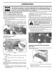
ASSEMBLY CHECK j / SEAT The tires on your tractor were overinflated at the factory for shipping purposes. Correct tire pressure is important for best cutting performance. • Reduce tire pressure to PSI shown on tires. / SWITCH CHECK PAD _ SLOT I / CHECK FOR PROPER POSITION OF BELTS TAPE See the figures that are shown for replacing motion and mower blade drive belts in the Service and Adjustments section of this manual. Verify that the belts are routed correctly. WiRiNG HARNESS Fig.
OPERATION These symbols may appear on your tractor or in literature supplied with the product. Learn and understand their meaning. REVERSE NEUTRAL HiGH L I\1 LOW CHOKE FAST SLOW iGNiTiON SWITCH ENGINE OFF REVERSE OPERATION SYSTEM (ROS) ENGINE ON ENGINE START PARKING BRAKE oi OVER TEMP LIGHT PARKING BRAKE LOCKED PARKING BRAKE UNLOCKED ,t FUEL ATTACHMENT CLUTCH DISENGAGED OiL PRESSURE ATTACHMENT CLUTCH ENGAGED BATTERY REVERSE FORWARD will indicates a hazard result in death WARNING
OPERATION KNOW YOUR TRACTOR READ THiS MANUAL AND SAFETY RULES BEFORE OPERATING YOUR TRACTOR Compare the illustrations with your tractor to familiarize yourself with the locations of various controls and adjustments. Save this manual for future reference. 03104 Fig. 5 Our tractors conform to the applicable safety standards of the American National Standards Institute. (A) ATTACHMENT LIFT LEVER - Used to raise and lower the mower or other attachments mounted to your tractor.
OPERATION The operation of any tractor can result in foreign objects thrown into the eyes, which can result in severe eye damage. Always wear safety glasses or eye shields while operating your tractor or performing any adjustments or repairs. We recommend standard safety glasses or a wide vision safety mask worn over spectacles. HOW TO USE YOUR TRACTOR TO SET PARKING BRAKE • Never use the choke to stop the engine.
OPERATION TO ADJUST MOWER CUTTING HEIGHT TO OPERATE (See Fig. 10) MOWER Your tractor is equipped with an operator presence sensing switch. Any attempt by the operator to leave the seat with the engine running and the attachment clutch engaged will shut off the engine. You must remain fully and centrally positioned in the seat to prevent the engine from hesitating or cutting off when operating your equipment on rough, rolling terrain or hills. • Select desired height of cut with attachment lift lever.
OPERATION REVERSE OPERATION • SYSTEM (ROS) Your tractor is equipped with a Reverse Operation System (ROS). Any attempt by the operator to travel in the reverse direction with the attachment clutch engaged will shut off the engine unless ignition key is placed in the ROS "ON" position. • Do not push or tow tractor at more than two (2) MPH. • To reengage transmission, reverse above procedure.
OPERATION TO START ENGINE PURGE (See Fig. 4) When starting the engine for the first time or if the engine has run out of fuel, it will take extra cranking time to move fuel from the tank to the engine. • Ensure freewheel control is in the transmission engaged position. • Sit on seat in operating position, depress clutch/brake pedal and set parking brake. • Place motion control lever in neutral position. • Move attachment clutch to "DISENGAGED" position. • Move throttle control to choke position.
OPERATION MOWING TIPS • Tire chains cannot be used when the mower housing is attached to tractor. • Mower should be properly leveled for best mowing performance. See "TO LEVEL MOWER HOUSING" in the Service and Adjustments section of this manual. The left hand side of mower should be used for trimming. Drive so that clippings are discharged onto the area that has been cut. Have the cut area to the right of the tractor. This will result in a more even distribution of clippings and more uniform cutting.
MAINTENANCE BEFORE EACH USE MAINTENANCE SCHEDULE EVERY 50 HOURS Check A T Check for Loose Fasteners Check/Replace Mower Blades Lubrication Chart 0 Check Battery Level R Clean Battery and Terminals Engine Enqine Oil (with oil filter) Change Engine Oil (without oil filter) v' Air Filter G Clean Air Screen Replace Clean Oil Filter Engine Replace v" _,2 (if equipped) v"2 V' Fins Plug Fuel Filter more often when operating under 2 - Service more often when operating in
MAINTENANCE BLADE TRACTOR Always observe maintenance. safety rules when performing CARE For best results mower blades must be kept sharp. Replace bent or damaged blades. any BRAKE OPERATION If tractor requires more than five (5) feet to stop at highest speed in highest gear on a level, dry concrete or paved surface, then brake must be checked and adjusted. (See "TO CHECK BRAKE" in the Service and Adjustments section of this manual).
MAINTENANCE V=BELTS OIL DRAIN VALVE Check V-belts for deterioration and wear after 100 hours of operation and replace if necessary. The belts are not adjustable. Replace belts if they begin to slip from wear. TRANSAXLE CLOSED AND ----_._ __Z_L-/_'_ LOCKED _"-['_-__ MAINTENANCE POSITION __._ DRA N The transmission fan and cooling fins should be kept clean to assure proper cooling. YELLOW Do not attempt to clean fan or transmission while engine is running or while the transmission is hot.
MAINTENANCE IN=LINE FUEL FILTER (See Fig. 19) DECK WASHOUT The fuel filter should be replaced once each season. If fuel filter becomes clogged, obstructing fuel flow to carburetor, replacement is required. • With engine cool, removefilter and plug fuel linesections. • Place new fuel filter in position in fuel line with arrow pointing towards carburetor. • Ensure there are no fuel line leaks and clamps are properly positioned. • Immediately wipe up any spilled gasoline.
SERVICE AND ADJUSTMENTS WARNING: TO AVOID SERIOUS iNJURY, BEFORE PERFORMING ANY SERVICE OR ADJUSTMENTS: * * * * TO REMOVE • • • • • • • MOWER iMPORTANT: IF AN ATTACHMENT OTHER THAN THE MOWER IS TO BE MOUNTED ON THE TRACTOR, REMOVE THE FRONT LINK (E) AND REAR LIFT LINKS (C) FROM TRACTOR AND HOOKTHE CLUTCH SPRING (Q) INTO THE CABLE GUIDE ON FRONT EDGE OF LOWER DASH. (See Fig. 22) Place attachment clutch in "DISENGAGED" position. Lower attachment lift lever to its lowest position.
SERVICE AND ADJUSTMENTS • • ATTACH MOWER SIDE SUSPENSION ARMS (A) TO CHASSIS - Position hole in arm over pin (B) on outside of tractor chassis and secure with retainer spring. Repeat on opposite side of tractor. • Insert end of link (E) into hole in front mower bracket and secure with washer and retainer spring (J). Fig. 25 • Fig. 23 • ATTACH REAR LIFT LINKS (C) - Lift rear corner of mower and position slot in link assembly over pin (D) on rear mower bracket and secure with washer and retainer spring.
SERVICE AND ADJUSTMENTS TO LEVEL MOWER Ensure tires are properly inflated to the PSI shown on tires. If tires are over or under inflated, it may affect the appearance of your lawn and lead you to think the mower is not adjusted properly. VISUAL SIDE-TO-SIDE ADJUSTMENT • If adjustment is necessary, see step in Visual Adjustment instructions above. • Recheck measurements, adjust if necessary until both sides are equal. FRONT-TO-BACK ADJUSTMENT (See Fig.
SERVICE AND ADJUSTMENTS TO REPLACE MOWER BLADE DRIVE BELT NOTE: Observe entire motion drive belt and position of all belt guides and keepers. (See Fig. 32) The mower blade drive belt may be replaced without tools. Park the tractor on level surface. Engage parking brake. • Remove belt from stationary idler (A) and clutching idler (B). BELT REMOVAL • Remove mower from tractor (See "TO REMOVE MOWER" in this section of manual). • Work belt off both mandrel pulleys and idler pulleys.
SERVICE AND ADJUSTMENTS TRANSAXLE MOTION CONTROL LEVER NEUTRAL ADJUSTMENT (See Fig. 34) TO ADJUST FRONT WHEEL TO REMOVE • • NOTE: If additional clearance is neededto getto adjustment bolt, move mower deck height to the lowest position. After above adjustment is made, if the tractor still creeps forward or backward while motion control lever is in neutral position, follow these steps: • Loosen the adjustment bolt. • Move the motion control lever 1/4" to 1/2" in the direction it is trying to creep.
SERVICE AND ADJUSTMENTS TO START ENGINE (See Fig. 36) WiTH A WEAK BATTERY REPLACING BATTERY (See Fig. 37) WARNING: Do not short battery terminals by allowing a wrench or any other object to contact both terminals at the same time. Before connecting battery, remove metal bracelets, wristwatch bands, rings, etc. Positive terminal must be connected first to prevent sparking from accidental grounding. WARNING: Lead=acid batteries generate explosive gases.
SERVICE AND ADJUSTMENTS TO REPLACE • • • HEADLIGHT BULB ENGINE Raise hood. Pull bulb holder out of the hole in the backside of the grill. Replace bulb in holder and push bulb holder securely back into the hole in the backside of the grill. Close hood. INTERLOCKS TO ADJUST CONTROL CABLE The throttle control has been preset at the factory and adjustment should not be necessary. If adjustment is necessary, see engine manual.
STORAGE ENGINE Immediately prepare your tractor for storage at the end of the season or if the tractor will not be used for 30 days or more. FUEL SYSTEM IMPORTANT: IT IS IMPORTANTTO PREVENT GUM DEPOSITS FROM FORMING IN ESSENTIAL FUELSYSTEM PARTS SUCH AS CARBURETOR, FUEL FILTER, FUEL HOSE, OR TANK DURING STORAGE. ALSO, EXPERIENCE INDICATES THAT ALCOHOL BLENDED FUELS (CALLED GASOHOL OR USING ETHANOLOR METHANOL) CAN ATTRACT MOISTURE WHICH LEADS TO SEPARATION AND FORMATION OFACIDS DURING STORAGE.
TROUBLESHOOTING CAUSE PROBLEM Wi[[ not start Out of fuel. 2. 3. 4. 5. 6. 7. Engine not "CHOKED" properly. Engine flooded. Bad spark plug. Dirty air filter. Dirty fuel filter. Water in fuel. 2. 3. 4. 5. 6. 7. 8. 9. Loose or damaged wiring. Carburetor out of adjustment. 8. 9. 10. Hard to start Engine turn will not over Engine clicks wi[[ not start Loss of power but Engine valves out of adjustment. 10. See "TO START ENGINE" in Operation section.
TROUBLESHOOTING CAUSE PROBLEM Engine continues to run when oper= ator leaves seat with attachment clutch CORRECTION 1. Check wiring, switches and connections. If not corrected, contact an authorized service center/ department. Worn, bent or loose blade. Mower deck not level. 1. 2. Replace blade. Tighten blade bolt. Level mower deck. 3. 4. Buildup of grass, leaves, trash under mower. Bent blade mandrel. 5. Clogged mower deck vent holes from buildup of grass, leaves, and trash around mandrels. 3.
SUGGESTED GUIDE FOR SIGHTING SLOPES FOR SAFE OPERATION ONLY RIDE UP AND DOWN NOT ACROSS HILL 15 DEGREES i_ HILL, MAX. down the face of slopes, never across the face. Do not mow WARNING: To avoid serious injury, operate your tractor up and slopes greater than 15 degrees. Make turns gradually to prevent tipping or loss of control. Exercise extreme caution when changing direction on slopes. 1. Fold this page along dotted line indicated above. 2.
Two-Year Limited Consumer Lawn Tractor Warranty Ariens Company (Ariens) warrants to the original purchaser that Ariens brand consumer tractors will be free from defects in material and workmanship for a period of two years after the date of purchase. An authorized Ariens dealer will repair any defect in material or workmanship, and repair or replace any defective part, subject to the conditions, limitations and exclusions set forth herein.
Exclusions • - items Not Covered Engines and engine accessories covered by this warranty. by This Warranty are covered only by the engine manufacturer's warranty and are not Parts that are not genuine Ariens service parts are not covered by this warranty.
Ariens Company 655 West Ryan Street Brillion, Wl 54110-1072 800-317-5898 www.ariens.com _IL WARNING _i_ The engine exhaust from this product contains chemicals known to the State of California to cause cancer, birth defects or other reproductive harm.
TRACTE HYDROSTATIQ Manuel de I'Op_rateur Modeles 936042 42" Tracteur __ _ FRAN_AIS De Hydrostatique 431471 Rev. 2 04.08.10 Imprim_ Aux E_.-U.
•_ Conseils pour I'utilisation f en toute f securite des tracteurs DANGER: CET TRACT.EUR PEUT AMPUTER LES MAINS, LES PIEDS ET PROJETER DES OBJETS. L_INOBSERVATION REGLES DE SECURITE SUIVANTES PEUT ETRE LA CAUSE DE BLESSURES SERIEUSES ET MEMES MORTELLES.
& f Conseils REGLES DE SECURITE pour I'utilisation en toute securite des tracteurs ill. ENFANTS ENTRETIEN Des accidents tragiques peuvent avoir lieu si I'op@ateur ne fait pas tres attention en presence d'enfants. Les enfants sont souvent tres attires par la machine et par la tonte. Ne croyez jamais que les enfants restent immobiles & I'endroit oQ vous venez de les taJsser. • Les enfants doivent se tenir hors de la zone de tonte et sous la supervision d'un adulte responsable, autre que I'op@ateur.
SPECIFICATIONS DE PRODUIT Capacite et le Type D'Essence: 3.0 Gallons (11,3 L) Lessence Sans Ptomb Normale Type D'Huile API-SG-SL): SAE 30 (Superieure De 32°F/0°C) SAE 5W-30 (Inferieure De 32°F/0°C) Capacite D'Huile: Avec Un Filtre 64 Oz. (1,96 L) Sans Filtre 60 Oz. (_1,77L) Champion QC12YO (Ecart: 0,040 Pc/1,020 mm) Bougie D'allumage: Vitesse de marche MPH/KPH) Marche En Avant: Marche En Arriere: Systeme De Chargement: Batterie: 3 Amps & Batterie 5 Amps & Lampoule des Phares AMPiHR: 28 MIN.
"% PIECES PAS ASSEMBLE f Volant de direction f % I _ J Insert du volant de direction (1) Rondelle Volant de direction t/"" , r- I 1 Adaptateur (1) Serrure Rondelle 1 % ', "_=_" ; Bo U Ion \ I ,I ,. J \--.._-_..
MONTAGE Votre nouveau tracteur a et6 monte & l'usine sauf les pieces qui ne sont pas montees pour I'expedition. Pour assurer I'utilisation correcte et sore de votre tracteur, toutes les pieces et la visserie que vous montez doivent @re serrees A fond. Utilisez les bons outils pour assurer un fonctionnement securitaire. LES OUTILS EXIGi'S POUR LE MONTAGE DE VOTRE TRACTEUR Un jeu de cle & douille rendra le montage. males des cles sont inscrites.
MONTAGE m VERIFIER INTERRUPTEUR//F _7 VC:RIFIER Sl TOUTES LES COURROIES CORRECTEMENT EN PLACE FENTE_ VERIFIER HARNAB DE FIL LE SI_:GE(Voir la Fig. 4) Empoignez la poignee de reglage et tirez vers le haut, glissez le siege b. la position desir6e et rel&chez la poignee de reglage. _MSTE FENTE.
UTILISATION Ces symboles peuvent se montrer sur votre tracteur ou dans les publications fournies avec le produit. signification des symbotes. EN ARRIE_RE POINT MORT HAUT L I\1 BAS E_TRANGLEUR COUPER SYSTI_ME DE FONCTIONNEMENT EN ,MARCHE ARRIERE DI_MARRER MOTEUR LE MOTEUR ALLUME_ FREIN LENTE RAPIDE ® 45 o, I LE MOTEUR Apprenez et comprenez ALLUMAGE FREIN DE STATIONNEMENT VERROUILLE" DE STATIONNEMENT O DI_VERROUILLI_ (ROS) , PAR DESSUS TEMPI_RATURE ESSENCE PRESSION DOHUILE BATTE
UTILISATION CONNAISSEZ AVANT VOTRE TRACTEUR D'UTILISER VOTRE TRACTEUR, LISEZ CE MANUEL ET LES REGLES DE SI_CURITE Comparez les illustrations ci-dessous & celles de votre tracteur afin de you familiariser avec I'emptacementdes differentes commandes et avec les reglages. Gardez ce manuel pour ref6rence. 031 04 Fig. 5 Nos tracteurs sont conformes aux normes de securit6 de I'American National Standards Institute.
UTILISATION L'utilisation d'un tracteur pr_sente le risque de projection des particules dana les yeux qui peuvent causer des blessures s_rieuses. Portez toujours des lunettes de s_curit_ ou une visi_re pendant que vous utilisez, ou que vous faites des r_glages ou des r_parations au tracteur. Nous recornrnandons des lunettes de s_curit_ ou un masque large de s_curit_ port_ au-dessus des lunettes. POUR ENGAGER STATIONNEMENT LE FREIN DE (Voir la Fig.
UTILISATION POUR RI'=GLER LA HAUTEUR DE COUPE LA TONDEUSE (Volt la Fig. 10) La position du levier d'accrochage la tonte. DE POUR UTILISER Votre tracteur est munJ d'un interrupteur de detection de presence d'un op@ateur. Le moteur s'arr@e si I'op@ateur essaie de quitter le siege pendant que le moteur fonctJonne et que l'embrayage d'accessoire est engage.
UTILISATION SYSTEME DE FONCTIONNEMENT MARCHE ARRIi_RE (ROS) EN REMARQUE: Pour proteger le capot des dommages pendant le transport de votre tracteur sur un camion ou une remorque, assurez-vous que le capot soit ferme et fixe au tracteur. Utilisez les moyens appropries (corde, c&ble, etc.). Votre tracteur est equip6 d'un Systeme de fonctionnement en marche arriere (ROS).
UTILISATION POUR DI_MARRER LE MOTEUR (Voir la Fig. 4) Si vous demarrez le moteur pour la premiere fois ou si le moteur est sans essence, il faudra plus de temps pour deptacer I'essence du reservoir au moteur. Assurez-vous que la commande roDe libre soit dans la position d'engrenage engagee. • Asseyez-vous sur le siege, enfoncez la pedale d'embrayage/ frein et engagez te frein de stationnement. • Mettez le levier de commande de deplacement a la position point mort.
UTILISATION CONSEILS DE TONTE • Les chaTnes de pneu ne peuvent pas _tre utitisees quand le carter de tondeuse est attache. • Assurez-vous que votre tondeuse soit correctement nivelee pour le meilleur rendement. (Voir la section de "Pour Niveler le carter de Tondeuse" sous Entretien et Reglages de ce manuel). Vous devez utiliser te c6te gauche de la tondeuse pour la taille. Conduisez de maniere a ce que I'herbe coupee soit deversee sur la zone qui a et6 tondue.
ENTRETIEN GUIDE D'ENTRETIEN Verifiez de frein le systeme Avant chaque usage Verifiez I'integrite C Affilez/Remplacez T Tableaude lubrification Toutes les 25 heures Toutes les 50 heures Toutes les 100 heures Chaque Avant saison I'entreposage iFi/ t,," Verifiezla pressiondes pneus T Verifiezle systeme de presence R d'operateur et le systeme del ROS.
ENTRETIEN TRACTEUR Observez toujours I'entretien. les regles FONCTIONNEMENT de securit6 DANGER: N'utilisez que les lames de rechange autoris_e par le fabricant de votre tondeuse.
ENTRETIEN COURROIES TRAPi_ZOJ'DALES SOUPAPE V@ifiez les courroies trapezoidates pour la det@ioration et I'usure apresl00 heures d'utilisation. Remplacez-les si necessaire. Les courroies ne sont pas reglables. Remplacez les courroies si elles glissent b.cause de I'usure. ENTRETIEN DE LA TRANSMISSION MOTEUR La transmission pas exige pour sion fuit ou doit autorise le plus BOUCHON JAUN__ _ . .--'" "V TuBE oE V, DANGE Fig.
ENTRETIEN SILENCIEUX RACCORD DE LAVAGE COUPE (Voir La Fig. 21) Inspectez le silencieux et le pare-etincelles (s'il y a lieu) et remplacez-les. IIs pourraient creer des risques d'incendie et/ou d'endommagement. FILTRE D'ESSENCE (Voir la Fig, 19) INSTALLI_ EN LIGNE FILTRE _ D'ESSENCE ----'-'"--X. _ iMPORTANT: Assurez-vous que la goulotte d'evacuation du tracteur N'EST PAS DIRIGCE vers la maison, le garage, les voitures en stationnement etc.
f REViSiON f ET REGLAGES OU REGLAGES. • Appuyez sur la p_dale de frein/embrayage et engagez le frein de stationnernent, ADVERTISSEMENT: POUR EVITER DES DOMMAGESenSERIEUX, AVANT DE FAIRE TOUS LES REVISIONS • Placez le levier de la cornrnande de rnouvernent position point mort. • Piacez I'ernbrayage d'accessoire en position d_bray_e (DISENGAGED), • Tournez la cl_ de contact & la position d'arr6t (STOP) et enlevez-ia. • Assurez-vous que les iarnes et toutes les pi_ces tournantes se soient arr_t_es.
f REViSiON f ET REGLAGES ° FI2EZ LES BRAS DE SUSPENSION LATE_RAU2 DE LA TONDEUSE AU CHASSIS - Placez rorifice du bras sur la tige (B) b. I'e2terieur du ch&ssis du tracteur et fi2ez solidement a I'aide d'une ressort-arr_toir. ° Rep6tez de rautre c6te du tracteur. • Inserez rautre embout de la bielle (E) darts l'orifice du support avant de la tondeuse (H) et fi2ez fermement b. I'aide d'une rondelle et d'un ressort-arr_toir (J). Fig. 25 • Fig.
f REViSiON POUR AJUSTER LE NIVEAU f ET REGLAGES LA TONDEUSE AJUSTEMENT AVANT/ARRII_RE (Voir la Fig. 30 et 31) IMPORTANT: La plateforme dolt @re au m_me niveau d'un c6te et de t'autre. Pour obtenir de meilleurs resuttats, les lames de la tondeuse doivent @re ajustees de sorte que la pointe avant est 1/8" a 1/2" Jnf@Jeure& la pointe arrJ@e Iorsque la tondeuse est & sa position la plus etev6e.
f REViSiON f ET REGLAGES POUR REMPLACER LA COURROIE DE LAME DE TONDEUSE (Voir la Fig. 32) INSTALLATION 1. La courroie d'entra_nement de lame de tondeuse peut _tre remplacee sans outils. Garez le tracteur sur un terrain plat. Engagez le frein de stationnement. 2. ENLEVER LA COURROIE • Enlevez la tondeuse du tracteur (voir "POUR ENLEVEZ LA TONDEUSE" dans cette section de ce manuel). • Manoeuvrez ta courroie loin des deux poulies de mandrin et des poulies de gaiet-tendeur.
f REViSiON f ET REGLAGES REGLAGE DU LEVIER DE CONTROLE DU DE LA BOJTE DE VITESSES (Voir la Fig. 34) POUR RI_GLER DIRECTION Le tevier de contr61e de la bo_te de vitesses est regt6 au moment de la fabrication et n'a donc pas besoin d'autres reglages.
f REViSiON POUR DEMARRER BATTERIE FAIBLE _ LE MOTEUR AVEC (Voir la Fig. 36) f ET REGLAGES UNE REPLACER POUR ATTACHER • • (Voir la Fig. 37) et & I'acide produisent des gaz explosifs. Gardez les _tincelles, les flammes, les VERTISSEMENT: plomb cigarettes, etc. loin Les desbatteries batteries. au Portez toujours des lunettes protectrices Iorsque vous _tes pr_ d'une batterie. Si votre batterie est trop faible pour demarrer le moteur, elle devrait _tre rechargee.
f REViSiON POUR REMPLACER PHARES • • • • LAMPOULE f ET REGLAGES DES MOTEUR POUR RI_GLER LE CABLE COMMANDE DES GAZ Soulevez le capot. Degagez de la douitle d'ampoule de I'orifice & I'arri@e de la calandre. Reinstallez l'ampoule dans la douille et poussez & fond la douilte d'ampouie dans I'orifice & l'arri@e de la calandre. Fermez le capot. VERROUS La commande des gaz a et6 pr6reglee & I'usine et un reglage ne devrait pas @re necessaire. Si un reglage est necessaire, voir le manuel du moteur.
ENTREPOSAGE MOTEUR Preparez immediatement votre tracteur pour l'entreposage & la fin de la saison ou si le tracteur ne sera pas utilise pendant une )@iode de 30 jours ou plus. SYSTEME IMPORTANT: C'EST TRES IMPORTANT D'I_VITER LA FORMATION DES DEPOTS DE GOMME DANS LE CARBURATEUR, LE FILTRE D'ESSENCE, LE TUYAU D'ESSENCE OU LE RESERVOIR D'ESSENCE PENDANT EENTREPOSAGE.
f GUIDE DE DEPANNAGE PROBLEME CAUSE Le moteur refuse de d_marrer Sans essence. 2. Le moteur n'est pas d6marr6 & froid correctement. 1. 2. Remplissez le r_servoir d'essence. Referez-vous & la section "POUR Dt_MARRER LE MOTEUR" dans la section fonctionnement. 3, Le moteur 3. Attendez quelques minutes avant d'essayer 4, Mauvaise 4. Remplacez la bougie d'allumage. 5. Filtre & air sale. 5. Nettoyez/remplacez 6, Filtre d'essence 6. Remplacez le filtre d'essence. 7, II y a de reau 7.
f GUIDE DE DEPANNAGE PROBLI_ME CAUSE Vibrations excessives de la tondeuse CORRECTION 1. Remplacez la lame. Serrez & fond le boulon de lame. 2. 3. Remplacez le mandrin de lame. Serrezlespi&cesl&ches. Remplacezlespiecesendommagees. Le systeme qui d@ecte la presence du conducteurest d6fectueux, 1. V6rifiez le c&blage, les interrupteurs et les connexions.Si le probl6me n'est pas corrig6, contactez un centred'entretien autorise. 1. La lame est usee, tordue ou I&che. 2.
GUIDE SUGG_RE POUR L'EVALUATION DES PENTES AFIN D'AlViELIORER LA SP'-CURITP'-D'UTILISATION TONDEZ LES PENTES EN iVlONTANT OU EN DESCENDANT MAIS, JAiVlAIS EN TRAVERS O_ 15 DEGRI_S MAX _ parall_lement _ la pente, jamais transversalement. N'affrontez pas de pentes de plus de vous blesser gravement, votre tracteur 15VERTISSEMENT: degr6s.
Garantie jardinage de deux ans pour les utilisateurs priv s de Tracteur La societ6 Ariens (Ariens) garantit I'acheteur d'origine que les produits tracteur des marques Afiens contre tout defaut de materiau et de main-d'ceuvre pendant une periode de deux ans suivant la date initiale d'achat. Un concessionnaire Ariens autorise reparera tout defaut de materiau ou de main-d'oeuvre et reparera ou remplacera toute piece defaillante, selon les conditions, limitations et exclusions indiqu6es ici.
Exceptions • et Limitations Les batteries ne sent garanties, au prorata, que pendant une periode de douze (12) mois apres la date d'achat. Pendant les premiers (90) jours de la garantie, une batterie defectueuse sera remplacee gratuitement. Si la periode de garantie applicable est superieure a 90 jeurs, Ariens couvrira le coot au prorata de toute batterie defectueuse, jusqu'a douze (12) apres la date d'achat. Exclusions Les moteurs et les accessoires ne les couvre pas.
Ariens Company 655 West Ryan Street Brillion, WI 54110-1072 800-317-5898 www.ariens.com AVERTISSEMENT L_chappement du moteur de ce produit contient des produits chimiques reconnus par I'Etat de Californie comme _tant la cause de cancer, malformations A la naissance ou autres troubles de la reproduction.