
Use and Care Guide
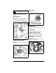
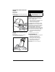
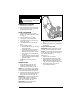
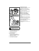
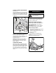

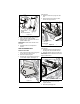
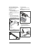
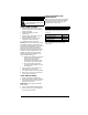
Table Of Contents
- Welcome
- Safety
- Practices & Laws
- Emission Control System
- Required Operator Training
- Safety Alert Symbol
- Signal Words
- Safety Decals
- Safety Rules
- Controls & Features
- Engine Switch
- Choke Control Knob
- Fuel Valve
- Primer Bulb
- Hour Meter
- Auger Control Lever
- Discharge Chute Handle
- Discharge Chute Rotation Lever
- Discharge Chute Deflector Lever
- Before Operation
- Check Engine Oil
- Operation
- Emergency Stopping
- Start The Engine
- Operate Unit
- Stop The Engine
- Transporting Unit
- For Best Performance
- Maintenance
- Maintenance Schedule
- Service Parts
- Clean Unit
- Check Engine Oil
- Change Engine Oil
- Check Fasteners
- Check Deflector Resistance
- Check Auger Paddle Wear
- Check Scraper Blade Wear
- Check Belt Wear
- Service & Adjustments
- Replace Auger Paddles
- Adjust Auger Cable
- Replace Drive Belt
- Replace Scraper Blade
- Storage
- Short Term Storage
- Long Term Storage
- Start-of-Season Fuel Preparation
- Accessories
- Troubleshooting
- Specifications
- Warranty
EN - 17
REPLACE SCRAPER BLADE
Replace scraper blade when worn too much
or with every other auger paddle
replacement.
Remove Scraper Blade
1. Stop engine and wait for all moving parts
to stop and for hot parts to cool.
2. Tip unit back onto handlebar bend. See
Figure 14.
NOTICE: DO NOT tip beyond bend or oil may
leak from engine.
See Figure 22.
3. Disconnect spring hooks from scraper
blade, remove from unit and discard.
4. Using a wrench, hold pivot rod stationary
and remove hardware retaining pivot rod
and blade. Retain hardware.
5. Remove pivot rod from scraper blade and
discard blade. See Figure 23.
Install Scraper Blade
1. Insert pivot rod through new scraper
blade.
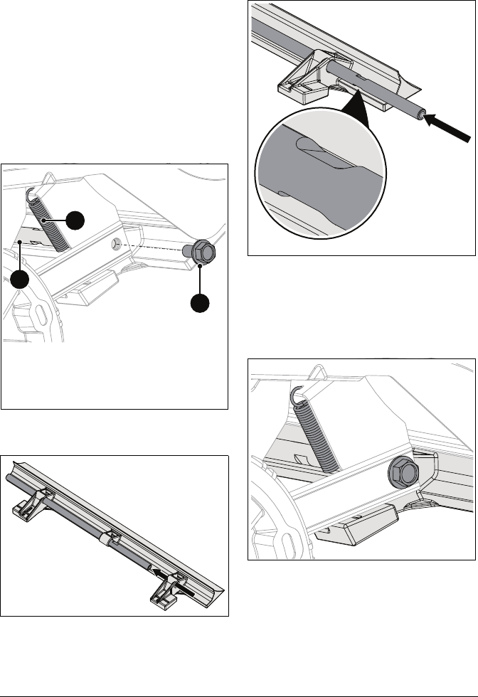
IMPORTANT: Reinstall pivot rod so wrench
flats are positioned toward the right side of
unit. See Figure 24.
See Figure 25.
2. Secure scraper blade assembly to
housing with original hardware.
3. Install spring hooks to frame and around
scraper blade. Make sure blade has
tension.
Figure 22
1. Spring
2. Scraper Blade
3. Pivot Rod
1
2
3
Figure 23
Figure 24
Figure 25