Sno-Thro ® Operator’s Manual Manuel du Utilisateur Professional 21 Models 938024 – SSR (SN 000101 +) 938025 – SSRC (SN 000101 +) E10 ENGLISH FRANÇAIS 05147700 • 7/17 Printed in USA
TABLE OF CONTENTS WELCOME . . . . . . . . . . . . . . . . . . . . . . 1 SAFETY. . . . . . . . . . . . . . . . . . . . . . . . . 2 Practices & Laws . . . . . . . . . . . . . . . . . . Emission Control System. . . . . . . . . . . . Required Operator Training . . . . . . . . . . Safety Alert Symbol . . . . . . . . . . . . . . . . Signal Words . . . . . . . . . . . . . . . . . . . . . Safety Decals. . . . . . . . . . . . . . . . . . . . . Safety Rules. . . . . . . . . . . . . . . . . . . . . .
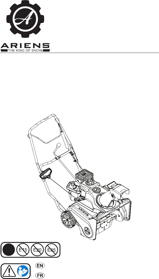
WELCOME Congratulations on your purchase and welcome to the Ariens family! Every machine in the Ariens lineup is designed for long-lasting and unsurpassed performance. We are confident your machine will be part of your family for many years to come. Have Questions or Need Assistance? ariensstore.com • arienscusthelp.com A parts manual for your unit is available for free download or purchase at ariens.com.
SAFETY WARNING: AVOID INJURY. This snow thrower is capable of crushing or amputating body parts. Failure to observe the safety instructions in the manuals and on decals could result in serious injury or death. ALWAYS disengage auger, stop unit and engine and allow moving parts to stop before leaving operator’s position. Read these safety rules and follow them closely.
4. Notice Safety Decal Descriptions NOTICE: Indicates information or procedures that are considered important but not hazard related. If not followed, property damage could result. 1. DANGER! 5. Important Danger! IMPORTANT: Indicates general reference information worthy of special attention. SAFETY DECALS The safety decals on your machine are visual reminders of the important safety information in this manual. All messages on your unit must be fully understood and carefully followed.
Training 2. DANGER! Danger! ROTATING PARTS. Keep clear of auger while engine is running. • Read Operator’s Manual. • Allow operation only by properly trained adult, never children. • Stop engine prior to leaving the operator’s position for any reason. • Keep all controls, guards and safety devices properly serviced and functional. • Never direct discharge towards persons or property that may be injured or damaged by thrown objects. 3.
Handle fuel with care; it is highly flammable. • Use an approved fuel container. • Never add fuel to a running engine or hot engine. • Fill fuel tank outdoors with extreme care. Never fill fuel tank indoors. • Never fill containers inside a vehicle or on a truck or trailer bed with a plastic liner. Always place containers on the ground, away from your vehicle, before filling. • When practical, remove gas-powered equipment from the truck or trailer and refuel it on the ground.
This product is equipped with an internal combustion type engine. Do not use unit on or near any unimproved, forest-covered or brush-covered land unless exhaust system is equipped with a spark arrester meeting applicable local, state or federal laws. A spark arrester, if it is used, must be maintained in effective working order by operator. Always maintain unit in safe operating condition. Damaged or worn out muffler can cause fire or explosion. Keep unit free of ice or other debris.
Use a slow speed to avoid stops or shifts on slopes. Avoid starting or stopping on a slope. Do not park unit on a slope unless absolutely necessary. When parking on a slope always block the wheels. Do not operate near drop-offs, ditches, or embankments. Unit can suddenly turn over if a wheel is over the edge of a cliff or ditch, or if an edge caves in. Fuel Do not run engine in an enclosed area. Always provide good ventilation. Fumes from engine exhaust can cause injury or death.
CONTROLS & FEATURES 11 1 2 16 12 3 14 4 9 6 7 10 15 17 13 5 8 Figure 3 1. 2. 3. 4. 5. 6. 7. 8. Handlebar Auger Control Lever Auger Control Cable Adjustment Plate Discharge Chute Rotation Lever (Model 938025) Discharge Chute Rotation Handle (Model 938024) Discharge Chute Deflector Lever Discharge Chute Auger Paddle 9. 10. 11. 12. 13. 14. 15. 16. 17.
WARNING: AVOID INJURY. Read and understand the Safety section before proceeding. FUEL VALVE See Figure 6. Controls fuel flow to the engine. See Figure 3 for all controls and features locations. On ENGINE SWITCH See Figure 4. Controls power to the engine. Engine switch must be in the run position to start and operate the engine. Engine will stop and will not start when switch is in the stop position. Off Figure 6 PRIMER BULB Run (On) Adds fuel to engine for easier starting on cold engines.
DISCHARGE CHUTE ROTATION LEVER BEFORE OPERATION Model 938025 See Figure 8. Rotates discharge chute left or right to control snow discharge. WARNING: AVOID INJURY. Read and understand the Safety section before proceeding. IMPORTANT: All references to left, right, front or rear are given from the perspective of operator in operator’s position, facing the direction of forward travel. 1. Know how to stop in an emergency. See Emergency Stopping on page 11. 2. Check for frozen components. 3.
OPERATION WARNING: AVOID INJURY. Read and understand the Safety section before proceeding. EMERGENCY STOPPING 1. Release auger control lever. 2. Push engine switch to the stop position. 3. Wait for all moving parts to stop before leaving operator’s position. START THE ENGINE 1. Position discharge chute in a safe direction. See Position Discharge Chute on page 11. 2. Turn fuel valve to the on position. 3. Push engine switch to run position. 4. Cold Engines Only: Turn choke control knob to on position. 5.
Model 938024 TRANSPORTING UNIT 1. Stop engine and wait for all moving parts to stop and for hot parts to cool. NOTICE: Use extra care when loading or unloading onto truck or trailer. DO NOT lift using discharge chute handle. 2. Secure unit chassis to transport vehicle. NOTICE: Never secure unit from rods or linkages that could be damaged. FOR BEST PERFORMANCE Model 938025 • For complete snow removal, walk slowly and slightly overlap each path previously taken.
MAINTENANCE WARNING: AVOID INJURY. Read and understand the Safety section before proceeding. Proper maintenance can prolong the life of unit. The Maintenance Schedule on Page 13 shows the recommended service schedule. Your Ariens dealer can provide service and adjustments to keep your unit operating at peak efficiency. Contact an authorized engine manufacturer’s service center for engine service. More frequent service may be required due to working conditions.
CHECK AUGER PADDLE WEAR SERVICE & ADJUSTMENTS See Figure 13. Check that paddles have not worn past wear indicator holes. Replace auger paddles when paddles have worn completely through wear indicator holes. See Replace Auger Paddles on page 14. WARNING: AVOID INJURY. Read and understand the Safety section before proceeding. IMPORTANT: All references to left, right, front or rear are given from the perspective of operator in operator’s position, facing the direction of forward travel.
See Figure 15. 4. Remove hardware retaining paddles to center plate and side plates. Discard all parts. IMPORTANT: DO NOT remove center plate. Figure 17 5. Rotate auger paddles by hand to ensure paddles are secure and do not interfere with housing. 6. Return unit to upright position. 7. Remove slack from auger cable. See Adjust Auger Cable on page 15. 8. Reconnect spark plug wire and turn fuel valve to the on position. Figure 15 Install Auger Paddles 1. Install spacers into paddle holes. See Figure 16.
See Figure 20. 4. Disconnect extension spring from idler arm. 5. Remove belt from drive sheave, idler sheave and engine sheave. 1 2 1 3 2 1. Plastic Sleeve 2. Z-hook 3. Adjustment Bracket 3 Figure 18 6. Start engine and engage auger control lever to ensure proper operation. 7. Release auger control lever and ensure paddle rotation stops. 1. Extension Spring 2. Idler Arm 3. Drive Belt Figure 20 IMPORTANT: Cable tension should not be excessive. 8. Reposition sleeve over adjustment bracket.
REPLACE SCRAPER BLADE Install Scraper Blade Replace scraper blade when worn too much or with every other auger paddle replacement. 1. Insert pivot rod through new scraper blade. Remove Scraper Blade 1. Stop engine and wait for all moving parts to stop and for hot parts to cool. 2. Tip unit back onto handlebar bend. See Figure 14. IMPORTANT: Reinstall pivot rod so wrench flats are positioned toward the right side of unit. See Figure 24. NOTICE: DO NOT tip beyond bend or oil may leak from engine.
START-OF-SEASON FUEL PREPARATION STORAGE WARNING: AVOID INJURY. Read and understand the Safety section before proceeding. Before opening the fuel valve for the first time after long-term storage, add fresh, stabilizertreated fuel to the fuel tank and any fuel containers with remaining fuel. ACCESSORIES SHORT TERM STORAGE 1. Engage auger momentarily to remove loose or melting snow to prevent auger shaft from freezing. 2. Tighten all hardware to correct specifications. 3.
TROUBLESHOOTING Problem Engine will not start. Probable Cause Correction Engine switch in stop position. Push engine switch to run position. See Engine Switch on page 9. Fuel valve is closed. Turn fuel valve to on position. See Fuel Valve on page 9. Fuel tank is empty. Fill fuel tank with fuel. See Before Operation on page 10. Engine not primed. Press the primer bulb twice. See Primer Bulb on page 9. Spark plug wire is disconnected. Connect spark plug. Refer to engine manual. Choke is off.
SPECIFICATIONS Model Number Description Engine Engine Model 938024 938025 Professional 21 SSR Professional 21 SSRC AX 208 Displacement – cm3 (in3) Maximum RPM – No load Oil Capacity – L (Pt.) Fuel Tank Capacity – L (Qt.) Fuel Octane Rating Starter Size and Weight Length – cm (in) Width – cm (in) Height – cm (in) Weight – kg (lb) 208 (12.7) 3600 ± 50 0.47 (1.0) 1.4 (1.5) See Engine Manual Recoil 129.0 (50.8) 53.8 (21.2) 105.9 (41.7) 39.5 (87.0) EN - 20 40.5 (89.
Sno-Thro®, Sno-Tek® and Finishing Tool Equipment Limited Warranty Warranty Ariens Company (Ariens) warrants to the original purchaser that Ariens, Gravely, Parker, and Countax ® ® brand chore-performing equipment (including Sno-Thro and Sno-Tek equipment) purchased on or after 1/1/2016 will be free from defects in material and workmanship for the time period noted in the chart below.
Exceptions and Limitations The chart below details special exceptions to this warranty: Warranty Code Warranty Period Use 1 Year All None Commercial These components are not covered when used commercially. Maximum 2 Years All Warranty is limited to 2 years for consumer use. (1 year for warranty code "PD".) Except as noted above, these components are covered for defect, not for wear. Maximum 2 Years All Warranty is limited on idlers to 2 years for consumer use.
Exclusions – Items Not Covered by This Warranty • Parts that are not genuine Ariens, Gravely, Parker or Countax service parts are not covered by this warranty and may void the warranty. • Damages resulting from the installation or use of any part, accessory, or attachment which is not approved by the Ariens Company for use with product(s) identified herein are not covered by this warranty.
655 West Ryan Street Brillion, WI 54110 ariensstore.com arienscusthelp.com parts.ariens.