Max Zoom™ Owner/Operator Manual Models 991085 – Max Zoom 48 991086 – Max Zoom 52 991087 – Max Zoom 60 ENGLISH FRANÇAIS 04276000A 10/10 Printed in USA
TABLE OF CONTENTS Safety . . . . . . . . . . . . . . . . . . . . . . . . . . . 4 Storage . . . . . . . . . . . . . . . . . . . . . . . . . 30 Assembly . . . . . . . . . . . . . . . . . . . . . . . 10 Accessories . . . . . . . . . . . . . . . . . . . . . 30 Controls and Features. . . . . . . . . . . . . 11 Service Parts . . . . . . . . . . . . . . . . . . . . 30 Operation . . . . . . . . . . . . . . . . . . . . . . . 12 Specifications . . . . . . . . . . . . . . . . . . . 31 Maintenance Schedule . .
NOTE: To locate your nearest Ariens Dealer, go to www.ariens.com. Serial Number Label DISCLAIMER Ariens reserves the right to discontinue, change, and improve its products at any time without public notice or obligation to the purchaser. The descriptions and specifications contained in this manual were in effect at printing. Equipment described within this manual may be optional. Some illustrations may not be applicable to your unit.
SAFETY WARNING: This cutting machine is capable of amputating hands and feet and throwing objects. Failure to observe the safety instructions in the manuals and on decals could result in serious injury or death. Slopes are a major factor related to loss-of-control and tip-over accidents. Operation on all slopes requires extra caution. Tragic accidents can occur if the operator is not alert to the presence of children. Never assume that children will remain where you last saw them.
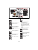
6 2 5 8 1 4 7 KEEP HANDS and FEET AWAY 02 98 81 00 3 2 OF1625 Figure 2 1. DANGER! TO AVOID SERIOUS INJURY OR DEATH Go up and down slopes, not across. DO NOT operate on slopes over 10°. Read Owner/Operator Manual. OL4450 • OL1801 • • Keep children and others away from unit while operating. • • OL4370 Never direct discharge toward other people. Thrown objects can cause injury. Remove objects that could be thrown by the blade.
Shut off engine, remove key, read manual before you adjust or repair unit. 8.CAUTION ! No Smoking OL4010 NO STEP! Always keep feet away from rotating parts. MAX. FILL Fill fuel tank to bottom of neck MAXIMUM. OL4420 3. WARNING! Do not operate mower unless guards are in operating position or bagger is attached. Always stand clear of discharge area.
Inspect unit before each use for: missing or damaged decals and shields, correctly operating safety interlock system, and deterioration of grass catchers. Replace or repair as needed. ALWAYS check overhead and side clearances carefully before operation. ALWAYS be aware of traffic when operating along streets or curbs. Keep children and people away. Keep children out of work area and under watchful care of a responsible adult. Keep area of operation clear of all toys, pets, and debris.
Always stand clear of the discharge area. ALWAYS disengage PTO, stop unit and engine, remove key, engage parking brake and allow moving parts to stop before leaving operator’s position. Never engage PTO while raising attachment or when attachment is in raised position. DO NOT operate at too fast a rate. DO NOT change engine governor settings or overspeed engine. Slow down before turning. DO NOT operate in reverse unless absolutely necessary. ALWAYS look down and behind before and while backing.
Keep the nozzle in contact with the rim of the fuel tank or container opening at all times until fueling is complete. Do not use a nozzle lockopen device. If fuel is spilled on clothing, change clothing immediately. Avoid Electric Shock. Objects contacting both battery terminals at the same time may result in injury and unit damage. DO NOT reverse battery connections. Reverse connections may result in sparks which can cause serious injury.
ASSEMBLY 4. Seat - See Seat Adjustments on page 13 and Service Position on page 18. 5. Position Steering Levers - Remove eccentric spacers and rotate steering levers to the operating position. Reinstall spacers. Tighten hardware securely. See Aligning the Steering Levers (Figure 14) on page 23. WARNING: AVOID INJURY. Read and understand entire Safety section before proceeding.
10. Check Safety Interlock System - Check to see that the interlock system operates correctly (See Safety Interlock System on page 12). 12. On 60-inch Decks: Remove the discharge chute from the transport position and place the discharge chute in the operating position. 13. Level Deck - Check unit to ensure deck level set at factory has been maintained (See Leveling the Mower Deck on page 28). 14. Check Function of all Controls - Ensure unit runs and performs properly.
OPERATION Steering Levers WARNING: AVOID INJURY. Read and understand entire Safety section before proceeding. A B C D CONTROLS AND FEATURES See Figure 4 for Controls and Features locations. 07757600B Safety Interlock System WARNING: Safety interlock system failure and improper operation of unit can result in death or serious injury. Test this system each time the unit is operated. If this system does not function as described, do not operate until repairs are made.
Throttle Lever The throttle lever changes the engine speed. Move the throttle lever to Fast (1) to increase engine speed. Move the lever to Slow (2) to decrease engine speed. 1 Cutting Height: Put cutting height adjustment pin in desired hole. Push mower lift pedal forward and hold it while pushing down on the lift lock. Slowly lower mower lift pedal until deck lift contacts cutting height adjustment pin. Fuel Shut-Off Valve Use this valve to control fuel flow from left or right fuel tank.
The alert starts counting down two hours before the maintenance is due. The meter flashes the word, "Now," when it reaches the maintenance time. Press and hold the toggle button to reset the maintenance clock to zero after perfoming the service. NOTE: The hour meter is preprogrammed for the initial oil change at 25 hours and for 100 hours thereafter. The hour meter is programmed for the initial hydraulic oil and filter change at 75hours and for 400 hours thereafter.
STOPPING IN AN EMERGENCY Fuel Stabilizer Gasoline left in the fuel system for extended periods without a stabilizer will deteriorate, resulting in gum deposits in the system. These deposits can damage the carburetor and the fuel hoses, filter and tank. Prevent deposits from forming in the fuel system during storage by adding a quality fuel stabilizer to the fuel. Follow the recommended mix ratio found on the fuel stabilizer container.
WARNING: Move the steering control levers slowly and keep the throttle control lever at slow speed until you learn how to operate the unit. 3. Bring the steering levers to neutral. 4. Slow the engine down to about 3/4 speed. 5. Turn ON the PTO switch to engage the mower. IMPORTANT: Never engage the PTO if the mower is plugged with grass or other material. This may cause damage to the electric clutch. 6. Move throttle control to fast. 7. Move the steering levers forward to obtain a slow ground speed. 8.
MAINTENANCE SCHEDULE Proper maintenance can prolong the life of unit. The following charts show the recommended service schedule. More frequent service may be required due to working conditions (heavy loads, high ambient temperatures, dusty conditions, or airborne debris). See the maintenance instructions in the Engine Manual for additional information. WARNING: AVOID INJURY. Read and understand entire Safety section before proceeding.
Period Service Task Each Use Follow Engine Manual Maintenance Schedule Perform scheduled engine maintenance. Refer to engine manual for detailed instructions. Every 25 Hours Check Mower Blades Check mower blades for wear. Sharpen or replace as needed. See Mower Blades on page 20. Check Air FIlter Check air filter for dirt. Clean as required. Follow Engine Manual for maintenance schedule. Lubricate Unit Oil all pivot points and pin connections. Grease lube fittings. See Lubricate Unit on page 22.
Check Hydraulic Fluid Level 2 1 Check the system with the unit cold and parked on a flat, level surface. Then run the unit for about one minute and recheck the levels. 2 To Add Hydraulic Fluid: 1. Remove the cap from the expansion tank. 2. Fill the expansion tank with 20W-50 engine oil with an SL API classification until oil level reaches the cold fill line on the tank. 3. Install the expansion tank cap and then purge the system. See Purging the Hydraulic System on page 20. 3 4 1. Service Position 2.
7. Fill with 20W-50 engine oil with an SL API classification until oil appears at the bottom of the drain plug (about 2 quarts per transaxle). Install the drain plug and tighten it to 180 lbf-in (20.3 N•m). 8. Repeat steps 1–7 for the other transaxle. 9. Follow the instructions in To Add Hydraulic Fluid: on page 19. MOWER BLADES 2 1 5. Start the engine and slowly move the steering levers in forward and reverse five or six times. 6. Stop the engine, check the oil level and add oil as needed. 7.
BATTERY Sharpen the Mower Blades CAUTION: DO NOT sharpen mower blades while on unit. An unbalanced mower blade will cause excessive vibration and eventual damage to unit. Check mower blade balance before reinstalling blades. NEVER weld or straighten bent blades. WARNING: AVOID INJURY. Read and understand entire Safety section before proceeding. 1. Remove mower blade from unit. Discard mower blade if: • More than 1/2 in. (1.27 cm) of metal is removed. • Air lifts become eroded. • Blade is bent or broken.
3. Connect positive (+) lead of charger to positive (+) terminal, and negative (–) lead to negative (–) terminal. 4. Charge battery according to charger and battery manufacturers’ instructions. 5. Replace battery. See Replace Battery on page 21. 2 1 Jump-Starting Ariens does not recommend jump-starting your unit. Jump-starting can damage engine and electrical system components. See your engine manual for more detailed information.
4. Start the engine, run engine at full throttle, and release the parking brake. 5. Move the steering levers from Forward to Reverse several times to make sure controls are free. Then return steering levers to neutral position. 6. Check wheel(s) for movement. NOTE: The right and left hydraulic pumps are adjusted the same way. 7. If a wheel moves, adjust the return to neutral mechanism on the hydraulic pump: a. Loosen the return to neutral screw on the pump. b.
ADJUSTING THE UNIT TO TRACK STRAIGHT ADJUSTING THE HEIGHT OF THE STEERING LEVER HANDLES The handles have three height positions (Figure 16). WARNING: Prior to adjusting the tracking of the unit, shut OFF engine, engage parking brake, and remove the ignition key. 2 Check and adjust tire pressure. Increase pressure on side unit tracks to. DO NOT exceed maximum recommended tire pressure (See Specifications on page 31).
Check Adjustment NOTE: Be sure to check the parking brake on both sides of the unit (Figure 17). 1. Engage parking brake and set both transmission bypass valves to the neutral position. See Moving the Unit with the Engine Off on page 16. 2. Push the unit forward. If the unit easily rolls forward the transmission brakes are not fully engaging. Tighten the brake cable to fully engage the brake lever on the transmission. CAUTION: DAMAGED OR WORN BELTS may result in injury and/or damage to unit.
4. Remove short mower belt from right blade spindle and from deck. Idler pivot bolt must be loosened slightly to gain clearance to remove belt from under idler pulley (Figure 19). 5. Arrange new mower belt(s) on deck (short belt first). Retighten short mower belt idler pivot bolt. Install belts on sheaves. Put belts onto center sheave last. NOTE: The PTO idler spring length range is 12.25 to 12.50 in. (31.0 to 31.8 cm) measured at a 3.0 in. (7.62 cm) cutting height.
Lowest Cutting Height 1 2 Highest Cutting Height 6 5 OF3590 Figure 22 Removing the Mower Deck 3 1. Remove PTO belt (See Replacing Mower Belts on page 25). WARNING: AVOID INJURY. Mower lift arms and mower lift pedal could cause severe injury if they are not locked before removing the mower deck. ALWAYS lock mower deck lift before removing the deck. 7 4 8 OF1631 1. 2. 3. 4. Hydro Belt Spring Idler Engine Sheave 5. Right Hand Hydrostat 6. Left Hand Hydrostat 7. Clutch 8. Clutch Anchor 2.
Check Blade Level and Pitch 1 5 1 2 2 3 4 1. Mower Lift Arm 2. Link Chain 3. Mower Mounting Arm 4. Mower Mounting Pin 5. Mower Lift Arms Locked Figure 23 OF3765 Installing the Mower Deck (Figure 23) 1. Slide mower deck under unit. 2. Connect mower mounting arms to deck with mower mounting pins. 3. Install link chains on the mower lift arms in the same holes they were removed from. 4. Install PTO mower belt (See Replacing Mower Belts on page 25). 5.
CLUTCH ADJUSTMENT Blade Side-to-Side Level Right Left Blade Front-to-Back Pitch Front Rear Rear Figure 24 Adjust Blade Height Level and pitch the mower with the height adjusters on each deck lift bracket (Figure 25). Loosen the jam nut on the deck lift bracket bolt about 1/4 turn to reduce clamp load on the height adjusters. Loosen the jam nut on the deck adjuster bolt and then turn the bolt clockwise to raise the deck or counterclockwise to lower the deck. Tighten both jam nuts.
ACCESSORIES STORAGE WARNING: AVOID INJURY. Read and understand entire Safety section before proceeding. SHORT TERM NEVER spray unit with high-pressure water or store unit outdoors. Inspect unit for visible signs of wear, breakage or damage. Keep all nuts, bolts and screws properly tightened and know unit is in safe working condition. Store unit in a cool, dry protected area. LONG TERM Clean unit thoroughly with mild soap and low pressure water and lubricate (See Lubricate Unit on page 22 in Maintenance).
SPECIFICATIONS Model Number Model 991085 991086 991087 Max Zoom 48 Max Zoom 52 Max Zoom 60 Engine Kawasaki Engine Model Number FR691 FR730 Engine Displacement in3 (cc) 44.3 (726) Governed RPM (May be different from maximum RPM) 3600 ± 75 Liquid or Air Cooled Air Speed Forward Maximum – mph (km/h) 8.0 (12.9) Reverse Maximum – mph (km/h) 4.0 (6.
Two-Year Limited Lawn and Garden Consumer Ride-On Warranty Ariens Company (Ariens) warrants to the original purchaser that Ariens, Gravely and Countax brand consumer products manufactured and sold by Ariens will be free from defects in material and workmanship for a period of two years after the date of purchase.
To find an Ariens or Gravely authorized service representative, contact Ariens at: 655 W. Ryan Street Brillion, WI 54110 (920) 756 - 2141 www.ariens.com www.gravely.com To find a Countax authorized service representative, contact Countax at: Countax Ltd Countax House Great Haseley Oxfordshire OX44 7PF 0800 597 7777 www.countax.com Exceptions and Limitations • Batteries are warranted only for a period of 12 months after date of purchase, on a prorated basis.
CALIFORNIA AND EPA (UNITED STATES ENVIRONMENTAL PROTECTION AGENCY) EVAPORATIVE EMISSION CONTROL WARRANTY STATEMENT YOUR WARRANTY RIGHTS AND OBLIGATIONS The CARB (California Air Resources Board), the EPA, and Ariens Company are pleased to explain the evaporative emission control system's warranty on your 2011 model year small off-road equipment. In California, new equipment that uses small off-road engines must be designed, built, and equipped to meet the State's stringent anti-smog standards.
(4.) (5.) (6.) (7.) (8.) (9.) Repair or replacement of any warranted part under the warranty provisions of this article must be performed at no charge to the owner at an authorized Ariens, Gravely, or Parker service representative. Notwithstanding the provisions of subsection (4) above, warranty services or repairs must be provided at authorized Ariens, Gravely, or Parker service representatives that are franchised to service the subject small off-road equipment.
Ariens Company 655 West Ryan Street Brillion, WI 54110-1072 920-756-2141 Fax 920-756-2407 www.ariens.com WARNING The engine exhaust from this product contains chemicals known to the State of California to cause cancer, birth defects or other reproductive harm.