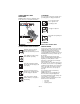
High Wheel Mower Owner/Operator Manual Manuel du Propriétaire/Utilisateur Model 911703 – PRO-24 HWSP Gasoline containing up to 10% ethanol (E10) or up to 10% MTBE (methyl tertiary butyl ether) is acceptable for use in this machine. The use of any gasoline exceeding 10% ethanol (E10) or 10% MTBE will void the product warranty. Il est possible d’utiliser de l’essence contenant jusqu’à 10% d’éthanol (E10) ou 10% de MTBE (éther méthyl-tertiobutylique) sur cette machine.
TABLE OF CONTENTS Safety . . . . . . . . . . . . . . . . . . . . . . . . . . . 4 Storage . . . . . . . . . . . . . . . . . . . . . . . . . 33 Assembly . . . . . . . . . . . . . . . . . . . . . . . . 9 Troubleshooting. . . . . . . . . . . . . . . . . . 34 Controls and Features. . . . . . . . . . . . . 14 Service Parts . . . . . . . . . . . . . . . . . . . . 35 Operation . . . . . . . . . . . . . . . . . . . . . . . 15 Accessories . . . . . . . . . . . . . . . . . . . . . 35 Maintenance . . . . . . .
DEALER DELIVERY • Record Unit Model and Serial numbers here: • Record Engine Model & Serial numbers here: PRODUCT REGISTRATION The Ariens dealer must register the product at the time of purchase. Registering the product will help the company process warranty claims or contact you with the latest service information. All claims meeting requirements during the limited warranty period will be honored, whether or not the product registration card is returned.
SAFETY CAUTION: POTENTIALLY HAZARDOUS SITUATION! If not avoided, MAY RESULT in minor or moderate injury. It may also be used to alert against unsafe practices. WARNING: This cutting machine is capable of amputating hands and feet and throwing objects. Failure to observe the safety instructions in the manuals and on decals could result in serious injury or death. Slopes are a major factor related to slip and fall accidents. Operation on all slopes requires extra caution.
SAFETY DECALS AND LOCATIONS 2. WARNING! ALWAYS replace missing or damaged safety decals. Refer to for safety decal locations. Do not operate mower unless guards are in operating position or bagger is attached. Do not operate mower unless guards are in operating position 1 RUN OFF 07700019A or bagger is attached. 2 Chock wheels if parking on a slope. 3 Figure 2 3. DANGER! 1. DANGER! KEEP HANDS AND FEET AWAY TO AVOID SERIOUS INJURY OR DEATH SAFETY RULES Read the operator’s manual.
Clear work area of stones, sticks, wire and foreign objects which might be picked up and thrown. Tall grass can hide obstacles. Know the work area. Stay alert for holes, rocks, rough terrain and hidden hazards. Keep away from drop-offs, ditches, or embankments that could cause operator to lose footing or control of unit. ALWAYS be aware of traffic when operating along streets or curbs. Keep work area clear of all persons, children and pets.
DO NOT mow at too fast a rate. DO NOT change engine governor setting or overspeed the engine. Do not operate mower on gravel or loose material such as sand. Stop mower when crossing drives, walks, or roads to prevent damage or injury from thrown objects. DO NOT pull mower backwards unless absolutely necessary. Look down and back, especially for small children, before and while moving backwards. On self-propelled models, releasing wheel drive control must stop mower’s forward movement.
Fuel and Fuel System Emission Control System Fuel is highly flammable and its vapors are explosive. Handle with care. Use only an approved gasoline container with an appropriately sized dispensing spout. • NO Smoking! • NO Sparks! • NO Flames! • Allow engine to cool before filling fuel tank. Gasoline with up to 10% ethanol (gasohol) or up to 10% MTBE (methyl tertiary butyl ether) is acceptable. Use of any gasoline other than those approved above will void the engine warranty. DO NOT OVERFILL.
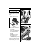
ASSEMBLY ASSEMBLY Handlebar CAUTION: AVOID INJURY. Read and understand the entire Safety section before proceeding. NOTE: The mounting hardware described in the following assembly procedures is factorymounted on the mower in the proper locations. Frame Handlebar Installation Handlebar Support 1. Remove mower, handlebar and discharge chute from carton. See Figure 3. Stud Figure 4 Support Clamp Handlebar Support Figure 3 2. Pull both handlebar supports back to vertical position. 3.
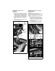
Wheel Drive Actuation Link Installation Operator Presence Control (OPC) Cable Installation See Figure 6. 10. Apply pressure against the wheel drive (self-propel) mechanism to hold it down against rear wheels. This will provide the required clearance to install the wheel drive actuation link on the bellcrank stud. 11. Install a flat washer, the actuation link and a second flat washer on bellcrank stud. 12. Install hairpin through bellcrank stud to secure actuation link. See Figure 7.
Throttle Cable Installation 7. Position throttle control (on handlebar) all the way forward (down) to the FAST position. 8. Push engine throttle lever fully forward until against its stop. The throttle lever may also be positioned against its stop by pulling the throttle cable froward. 9. Tighten the slotted hex cap screw to secure the clamp on the cable, securing the cable in place. 10. Install two cable ties to secure the OPC and throttle cables. See Figure 9.
Cable Tie Support Clamp Handlebar Rope Guide Closed Recoil Rope Mounting Cap Screw Rope Guide Opened Handlebar Support Cable Tie Figure 10 2. Position recoil rope in upper half of guide and then rotate lower half back to close guide, capturing rope. See Figure 10.
Discharge Chute Installation 6. Align front of chute and support plate with hole in deck and install round head square neck bolt and flanged lock nut. See Figure 14. 7. Tighten chute mounting hardware installed in steps 5 and 6. 1. Place mower in the Service Position. See SERVICE POSITION on page 20. 2. Remove flanged lock nut and round head square neck bolt from front of discharge chute. See Figure 12.
CONTROLS AND FEATURES 4 3 5 1 2 8 7 4 6 9 11 10 13 12 Figure 15 1. Operator Presence (Engine/Blade) Control 2. Recoil Starter Handle 3. Wheel Drive Control Handlebars 4. Engine Throttle Control 5. Air Filter 6. Fuel Tank and Cap 7. Upper (Wheel Drive) Guard 8. Discharge Chute 9. Lower Guard 10. Fixed Front Wheels (Standard) 11. Oil Fill/Dipstick 12.
OPERATION Recoil Starter Handle WARNING: Improper operation can lead to injury. Learn what the controls do and how they work. Thoroughly read and understand entire Operator Manual. When pulled, recoil starter handle will turn engine over. Engine Throttle Push throttle forward to increase engine speed. Pull throttle backward to decrease engine speed. CAUTION: DO NOT operate mower unless side discharge deflector is installed. Thrown objects may cause damage or injury.
3. Place throttle control in the high-speed position (all the way forward). 4. With operator presence control lever held against the handlebar, grasp starter handle and pull rope slowly until it pulls harder. This is the compression stroke. 5. Pull rope with rapid continuous full arm stroke to start engine. Allow rope to rewind slowly. IMPORTANT: DO NOT let starter handle snap against bracket. 6. Repeat step 4 and step 5 until engine starts. (If engine does not start, see TROUBLESHOOTING on page 34.
HEIGHT OF CUT ADJUSTMENT Height of Cut (HOC) is adjusted by positioning the front and rear wheels in a series of mounting holes. See Figures 18 and 19. 5. Hold rear axle bolt stationary with a wrench while removing outer lock nut. See Figures 17 and 18. Axle Bolt Outer Nut Inner Nut Inside View DANGER: Avoid injury from rotating blade. ALWAYS shut off engine, wait for moving parts to stop and allow engine to cool before adjusting height of cut.
Frame Height of Cut Holes Wheel Axle Bolt Inside View The height of the standard, fixed front wheels is changed by raising or lowering wheels in the four available mounting holes in each wheel support. Place wheels in upper holes for a lower cut and lower holes for higher cut. NOTE: Height-of-cut holes are spaced approximately 0.665" (17mm) apart. The mower is set-up at the factory in the second from the lowest position, for a 2.7" (69mm) cut height. 5.
MAINTENANCE MAINTENANCE SCHEDULE CAUTION: AVOID INJURY. Read and understand the entire Safety section before proceeding. NOTE: Some working conditions (heavy loads, high ambient temperatures, dusty conditions, or airborne debris) may require more frequent service. See engine manual for further maintenance and troubleshooting information. Ariens Dealers will provide any service, parts or adjustments which may be required to keep your unit operating at peak efficiency.
SERVICE POSITION Install Mower Blade Put unit into service position for easy access to underneath the deck. NOTE: Ensure blade air lift points upward. See Figure 20. 1. Replace blade, flat washer and lock nut on shaft. 2. Torque lock nut to 187 – 253 lb-ft (254 – 343 N•m). 3. Connect spark plug wire to spark plug. CAUTION: Avoid fuel spills. Follow steps below to help prevent fuel spills. If fuel leaks into air cleaner, replace air cleaner. ALWAYS clean up any spilled fuel. Sharpening Mower Blades 1.
CHECK FASTENERS DO NOT sharpen to this pattern. 2 1 Check all fasteners for proper tightness. Pay special attention to blade hardware and all guards, shields and safety devices. CHECK DRIVE BELTS 3 OT0792 Sharpen to this pattern. Check tension of mower blade and wheel drive belts. See BELT TENSION ADJUSTMENT on page 27. Check drive belts for wear and/or damage and replace as necessary. See BELT REPLACEMENT on page 30. GENERAL LUBRICATION DISCARD If More Than 1/2 in. (1.
REPLACE OIL FILTER CHECK MUFFLER Replace oil filter every 50 hours of use or annually. 1. Clean dirt and debris from oil filter and surrounding area. 2. Place mower in the Service Position. See SERVICE POSITION on page 20. 3. Place a suitable container below engine oil fill tube and remove cap to allow oil to drain from tube. 4. Turn oil filter counterclockwise to remove. See Figure 23. 5. Apply a thin coat of oil onto seal of new filter. 6. Install new filter and hand tighten securely. 7.
SERVICE AND ADJUSTMENTS To install a guard: 1. Position guard on mower and slide bolts with captive nyloc nuts into mounting brackets. 2. Thread each mounting bolt into mounting bracket and tighten securely. 3. Connect spark plug wire to spark plug. CAUTION: AVOID INJURY. Read and understand the entire Safety section before proceeding. WHEEL DRIVE ADJUSTMENTS Drive Belt Guard See Figure 27 DANGER: Avoid injury from rotating blade.
Wheel Drive Speed Adjustment The wheel drive lower belt connects the mower blade shaft to a variable speed (VS) pulley. Wheel drive speed is determined by how deep the wheel drive lower belt rides in the VS pulley. The higher the belt rides in the VS pulley groove, the slower the wheel drive speed. The lower the belt rides in the VS pulley groove, the faster the wheel drive speed. See Figures 24 and 25. 1. Remove both the upper and lower guards. See WHEEL DRIVE ADJUSTMENTS Drive Belt Guard on page 23. 2.
Wheel Drive Traction Adjustment The gap (clearance) between the drive rollers and tires, when wheel drive is disengaged, is used to set the amount of contact force (traction) when wheel drive is engaged. Drive roller to wheel gap should be 1/8" – 1/4" (3mm – 6mm). NOTE: A smaller gap between rollers and tires when wheel drive is disengaged provides for more engaged traction, which is helpful on sloped terrain.
Fine Adjustment Knob See Figure 27 Adjustment Link Wheel Drive Frame Engage Plate Washer Figure 26 GB - 26 Hairpin Bell Crank
5. While holding adjustment bolt stationary with a wrench, tighten flanged nut against adjustment bracket. 6. Tighten flanged lock nut and bolt attaching each adjustment plate to the adjustment bracket. 7. Install both the upper and lower guards. See WHEEL DRIVE ADJUSTMENTS Drive Belt Guard on page 23.
Adjust Wheel Drive Upper Belt Tension Wheel Drive Frame The wheel drive upper belt connects the variable speed (VS) pulley to the drive rollers shaft. 1. Remove both the upper and lower guards. See WHEEL DRIVE ADJUSTMENTS Drive Belt Guard on page 23. NOTE: The bearing holders slide vertically on the wheel drive frame. 2. Loosen two flanged lock nuts and round head square neck bolts securing each bearing holder to wheel drive frame. Do not remove mounting hardware. See Figure 29.
Adjust Mower Blade Drive Belt Tension 1. Remove lower guard. See WHEEL DRIVE ADJUSTMENTS Drive Belt Guard on page 23. 2. Loosen the four flanged lock nuts from the round head square neck bolts that secure the engine mounting plate to the mower frame. Do not remove hardware. See Figure 30. Mounting Bolts Flanged Nyloc Nut Belt Tensioning Bolt Engine Mounting Plate Mower Frame Engine Mounting Plate Figure 31 Frame Figure 30 3.
BELT REPLACEMENT Adjustment Plate Adjustment Bracket Wheel Drive Lower Belt Replacement See Figure 32. The wheel drive lower belt connects the blade shaft top pulley to a variable speed (VS) pulley. 1. Remove both the upper and lower guards. See WHEEL DRIVE ADJUSTMENTS Drive Belt Guard on page 23. NOTE: The adjustment bracket bolt holes are threaded. 2. Loosen the lock nut and bolt attaching each adjustment plate to the adjustment bracket. Do not remove hardware.
Wheel Drive Upper Belt Replacement See Figure 33. The wheel drive upper belt connects the variable speed (VS) pulley to the drive rollers shaft. 1. Remove wheel drive lower belt. See Wheel Drive Lower Belt Replacement on page 30. NOTE: The bearing holders slide vertically on the wheel drive frame. 2. Loosen two flanged lock nuts and round head square neck bolts securing each bearing holder to wheel drive frame. Do not remove mounting hardware. 3. Push drive rollers shaft down to release belt tension. 4.
Mower Blade Drive Belt Replacement 1. Remove wheel drive lower belt. See Wheel Drive Lower Belt Replacement on page 30. 2. Loosen the four flanged lock nuts from the round head square neck bolts that secure the engine mounting plate to the mower frame. Do not remove hardware. See Figure 34. Mounting Bolts Flanged Nyloc Nut Belt Tensioning Bolt Engine Mounting Plate Blade Drive Belt Mower Frame Frame Figure 35 Engine Mounting Plate 9. Install wheel drive lower belt.
STORAGE Engine CAUTION: AVOID INJURY. Read and understand the entire Safety section before proceeding. When storing unit for extended periods of time, remove all fuel from tank and carburetor (run dry). Refer to Engine Manual. IMPORTANT: NEVER spray unit with highpressure water or store unit outdoors. Store mower in a cool, dry, protected location. Cleaning Allow unit to cool. Clean unit thoroughly with mild soap and low pressure water. Brush off dirt and debris from all surfaces.
TROUBLESHOOTING PROBLEM PROBABLE CAUSE CORRECTION Engine will not start 1. Fuel tank empty or low. Engine is difficult to restart 1. Mower clogged with grass. 1. Clear clippings from under mower. (Allow the mower to clear clippings before shutting off engine.) Cut is poor 1. Worn blade. 1. Check blade (see SERVICE POSITION on page 20). 2. Too much grass is being removed per cutting. 2. Raise cutting height. (see HEIGHT OF CUT ADJUSTMENT on page 17) 3. Allow grass to dry. 4. Mow slower.
PROBLEM Wheel drive does not engage PROBABLE CAUSE CORRECTION 1. Wheel drive control not engaged. 2. Wheel drive belts tension too loose. 1. Engage wheel drive control. 2. Check wheel drive belts tension. Adjust as necessary (see BELT TENSION ADJUSTMENT on page 27). 3. Replace belt. (see BELT REPLACEMENT on page 30) 4. Check wheel drive control linkage. Adjust or replace as needed. See CHECK WHEEL DRIVE CONTROL The unit must stop quickly and completely when the control is released.
SPECIFICATIONS Model Number 911703 Description PRO 24HWSP Length – in. (cm) 60 (152.4) Height – in. (cm) 39 (99) Width – in. (cm) 24 (61) Actual Weight – lbs (kg) 152 Cutting Width – in. (cm) 24 (61) Cutting Height – in. (cm) 2–4 (5.1 – 10.2) Briggs & Stratton Professional Series EPA/CARB Compliant Engine, 4 cycle Ready Start 8.50 Gross Torque Engine Model Max Rotation Speed of Cutting Edge – feet per minute 15,400 Governed RPM (May be different from maximum rpm.
Commercial Mowing Equipment Limited Warranty Ariens Company (Ariens) warrants to the original purchaser that Ariens, Gravely and Countax brand products purchased on or after 1/1/2012 and designated or labeled commercial products by Ariens Company will be free from defects in material and workmanship for the time period noted in the chart below.
Exceptions and Limitations The chart below details special exceptions to this warranty: Warranty Code Warranty Exception Warranty Period Use Detail All Batteries 1 Year All Prorated All Belts, Muffler, Tires None Commercial All Cloth, Plastic, and Rubber Components (Including Belts and Cables) Maximum 2 Year All Warranty is limited to 2 years for consumer use. Except as noted above, these components are covered for defect, not for wear.
Disclaimer Ariens Company may from time to time change the design of its products. Nothing contained in this warranty shall be construed as obligating the Ariens Company to incorporate such design changes into previously manufactured products, nor shall such changes be construed as an admission that previous designs were defective.
CALIFORNIA AND EPA (UNITED STATES ENVIRONMENTAL PROTECTION AGENCY) EVAPORATIVE EMISSION CONTROL WARRANTY STATEMENT YOUR WARRANTY RIGHTS AND OBLIGATIONS The CARB (California Air Resources Board), the EPA, and Ariens Company are pleased to explain the evaporative emission control system's warranty on your 2012 model year small off-road equipment. In California, new equipment that uses small off-road engines must be designed, built, and equipped to meet the State's stringent anti-smog standards.
(4.) (5.) (6.) (7.) (8.) (9.) Repair or replacement of any warranted part under the warranty provisions of this article must be performed at no charge to the owner at an authorized Ariens, Gravely, or Parker service representative. Notwithstanding the provisions of subsection (4) above, warranty services or repairs must be provided at authorized Ariens, Gravely, or Parker service representatives that are franchised to service the subject small off-road equipment.
Ariens 655 West Ryan Street Brillion, WI 54110 920-756-2141 Fax 920-756-4688 www.ariens.