926 Series Sno-Thro® Owner/Operator Manual Manuel Du Propriétaire/Utilisateur Models 926037 – Pro 26 926038 – Pro 28 926039 – Pro 32 926040 – Pro 36 926041 – Pro-Track 26 926042 – Pro-Track 28 926043 – Pro-Track 32 926104 – Pro 32 12V 926105 – Pro 36 12V ENGLISH FRANÇAIS 03882900D 8/10 Printed in USA
TABLE OF CONTENTS SAFETY. . . . . . . . . . . . . . . . . . . . . . . . . . 4 STORAGE . . . . . . . . . . . . . . . . . . . . . . . 33 ASSEMBLY . . . . . . . . . . . . . . . . . . . . . . . 8 SERVICE PARTS . . . . . . . . . . . . . . . . . 33 CONTROLS and FEATURES . . . . . . . . 12 ACCESSORIES. . . . . . . . . . . . . . . . . . . 33 OPERATION . . . . . . . . . . . . . . . . . . . . . 13 TROUBLESHOOTING . . . . . . . . . . . . . 34 MAINTENANCE . . . . . . . . . . . . . . . . . . 20 SPECIFICATIONS .
DISCLAIMER Serial Number Label Ariens reserves the right to discontinue, make changes to, and add improvements upon its products at any time without public notice or obligation. The descriptions and specifications contained in this manual were in effect at printing. Equipment described within this manual may be optional. Some illustrations may not be applicable to your unit.
SAFETY NOTATIONS WARNING: To avoid injury to hands and feet, always disengage clutches, shut off engine, and wait for all movement to stop before unclogging or working on snow thrower. Hand contact with the rotating impeller is the most common cause of injury associated with snow throwers. Never use your hand to clean out the discharge chute. Keep hands and feet away from auger and impeller. NOTE: General reference information for proper operation and maintenance practices.
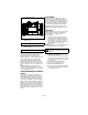
1. WARNING! 3. DANGER! Read Owner/Operator Manual. OL1801 OS2080 OL4370 Keep people away from unit while operating. Keep children out of work area and under watchful care of a responsible adult. Never direct discharge towards persons or property that may be injured or damaged by thrown objects. OL0910 Stop engine, remove key, read manual before making any repairs or adjustments. OL4010 Wear appropriate hearing protection. OL4690 ONLY use clean-out tool to clear blockages. NEVER use your hands. 2.
NEVER allow children to operate or play on or near unit. Be alert and shut off unit if children enter area. DO NOT allow adults to operate unit without proper training. Only trained adults may operate unit. Training includes actual operation. Keep area of operation clear of all toys, pets, and debris. Thrown objects can cause injury. Check for weak spots on docks, ramps or floors. Avoid uneven work areas and rough terrain. Stay alert for hidden hazards.
Check clutch and brake operation frequently. Adjust and service as required. All motion of drive wheels and auger/impeller must stop quickly when control levers are released. DO NOT operate on steep slopes. DO NOT clear snow across the face of slopes. Keep all movement on slopes slow and gradual. DO NOT make sudden changes in speed or direction. Use a slow speed to avoid stops or shifts on slopes. Avoid starting or stopping on a slope. DO NOT park unit on a slope unless absolutely necessary.
NEVER store unit with fuel in fuel tank, inside a building where any ignition sources are present such as hot water heaters, space heaters, or clothes dryers. Allow the engine to cool before storing in any enclosure. Shut off fuel and allow engine to cool completely before storing in closed area or covering unit. For extended storage, clean unit thoroughly. See Engine Manual for proper storage. Use only attachments or accessories designed for your unit. Check components frequently.
Install Discharge Chute and Discharge Chute Rod (Figure 5, 6, 7 and 8) 1. Grease underside of discharge chute ring (if not already greased). 2. Remove mounting hardware from auger housing. 3. Install discharge chute over opening in the auger housing. Finger tighten the mounting hardware removed in step 2. NOTE: Leave discharge chute pedestal loose to help install the chute rod and connect it to the control assembly. 1 7.
9. Connect the chute lock cable to the lock arm by fitting the cable ball end into the slot on the lock arm and then insert the chute lock cable fitting into the bracket on the chute pedestal (Figure 8). 10. Adjust and tighten jam nuts on cable to remove cable slack. Be sure not to pretension lock arm so it retracts from the gear teeth see Discharge Chute Control on page 25.
Check Function of Dual Handle Interlock Check Track Tension (926041, 042, 043) Without the engine running, press down (engage) both clutch levers. Release attachment clutch lever. Attachment clutch should remain engaged until traction clutch lever is released, then both clutches must disengage. If they do not, contact your Dealer for repairs. Check tracking of unit with the differential locked, and tension of tracks (see Track Tension Adjustment on page 32).
CONTROLS AND FEATURES 30 27 34 13 26 14 12 29 11 18 24 20 17 29 19 15 3 6 7 2 5 25 31 32 4 30 23 16 26 22 21 28 18 1 20 8 24 19 17 35 4 25 9 33 32 10 1. Oil Drain 2. Fuel Shut-Off Valve 3. Primer Bulb 4. Recoil Starter Handle 5. Throttle (Engine Stop) 6. Choke Control Knob 7. Ignition Key (Push/Pull) 8. Fuel Tank and Cap 9. Oil Fill/Dipstick 10. Electric Starter 11. Attachment Clutch Lever 12. Speed Selector 13. Traction Drive Clutch Lever 14. Deflector Remote Control 15.
OPERATION Attachment Clutch Right Hand Lever WARNING: AVOID INJURY. Read and understand the entire Safety section before proceeding. Squeeze Attachment Clutch Lever against handlebar (1) to engage attachment. Release both clutch levers (2) to disengage power and apply brake to attachment. 1 IMPORTANT: If the belt squeals when the attachment clutch lever OL2691 is engaged, the impeller may be frozen in the auger housing.
Speed Selector Snow Clean-Out Tool Position the Speed Selector in the appropriate speed notch to control forward and reverse travel. Forward: (6) Fastest 6 (1) Slowest Reverse: (1) Slow (2) Fast IMPORTANT: DO NOT change motion from 1 forward to reverse with clutch engaged. Forward speed can be 1 changed without declutching. 2 (Figure 11) WARNING: Hand contact with the rotating impeller is the most common cause of injury associated with snow throwers. Never use your hand to clean out the discharge chute.
Discharge Chute Control Differential Lock Knob (Figure 12) IMPORTANT: If chute does not stay in set position, adjust as directed in Discharge Chute Control on page 25, or repair before operation. Rotate the Chute with Discharge Chute Control (Figure 12). 1 OS7105 Figure 12 2 IMPORTANT: DO NOT force frozen chute controls. If frozen, take to warm place until controls are free.
Drift Cutters (Figure 14) Drift cutters break up snow drifts that are taller than the auger housing and direct the snow into the auger. Store the drift cutters on the auger housing when not in use. Install them as shown below so they are taller than the snow to be cleared. Track Angle (926041, 042, 043) (Figure 15) The track angle can be adjusted to position the auger housing for level clearing, deep cutting or transport.
FILLING FUEL TANK Fuel Shut-Off Valve WARNING: AVOID INJURY. Read and understand the entire Safety section before proceeding. 1 GASOLINE IMPORTANT: ALWAYS use gasoline that meets the following guidelines: • Clean, fresh gasoline. • A minimum of 87 octane/87 AKI (91 RON). High altitude use may require a different octane. Consult your engine manual. • Gasoline with up to 10% ethanol (gasohol) or up to 10% MTBE (methyl tertiary butyl ether) is acceptable.
4. Check Axle Lock (926041, 042, 043) Use the axle lock knob to lock or unlock the right side differential. Lock the differential to engage both tracks and increase traction; unlock the right side to allow for easier turning of the unit (see Differential Lock on page 15). 5. Check Skid Shoes Check and adjust Skid Shoes (See Skid Shoes on page 23). Allow 1/8 in. (3 mm) between scraper blade and hard, smooth surface(s). Allow 1 in. (25 mm) between scraper blade and uneven or gravel surfaces. 6.
12. Set throttle to Part Throttle or Slow position for adaptation to outside temperature or travel. Set throttle to Fast position for normal operation. IMPORTANT: DO NOT overload unit capacity by attempting to clear snow at too fast a rate. Use slow speed to clear deep or hard packed snow. Electric Start (12V) (926104, 105) Tips for Operation 1. Turn discharge chute straight ahead. 2. Make sure that the traction clutch and attachment drive clutch levers are fully disengaged. 3.
MAINTENANCE Ariens Dealers will provide any service or adjustments which may be required to keep your unit operating at peak efficiency. Should engine service be required, contact an Ariens dealer or an authorized engine manufacturer's service center. Service Position WARNING: AVOID INJURY. Read and understand the entire Safety section before proceeding. SERVICE POSITION (Figure 16) WARNING: Before tipping unit up onto housing, remove fuel so no spills will occur and remove battery (if equipped).
MAINTENANCE SCHEDULE CHECK CLUTCH OPERATION The chart below shows the recommended maintenance schedule that should be performed on a regular basis. More frequent service may be required. Auger / impeller must stop within 5 seconds when attachment clutch/impeller brake lever is released. Wheels must stop quickly when traction drive clutch lever is released. If clutches do not engage or disengage properly, adjust or repair before operation.
To ensure adequate lubricant level: 1. Remove filler plug. Lubricant must be at least up to bottom of lubricant filler hole with unit resting on a level-surface. 2. Add lubricant if required. Allow oil to drain to level of plug and replace plug. IMPORTANT: Use only Ariens L-3 synthetic severe duty gear lube (Part Number 00068800). NOTE: Gearcase filler plug may require an application of Loc-Tite® 565 thread sealant with repeated servicing.
Replace Fuse (926104, 105) 3. Install a new fuse of the same amprating and type. 1. Remove the two screws and the cover plate from beneath the battery. Fuse and fuse holder. OS7455 Figure 20 Cover plate and mounting screws. Figure 19 OS7450 2. Locate the fuse holder on the wiring harness and remove the fuse. 4. Replace the cover plate and secure in position with the two screws removed in step 1. NOTE: Make sure the wire harness does not get pinched between the cover plate and the auger housing.
SHEAR BOLTS 5. Secure handlebar to frame with hardware removed in step 4 using the different hardware locations shown in Figure 23. (Figure 22) IMPORTANT: Use only Ariens shear bolts for replacement. Use of any other type of shear bolt may result in severe damage to unit. See SERVICE PARTS on page 33. Occasionally a foreign object may enter the auger/impeller housing and jam the auger, breaking shear bolts which secure the auger to the shaft.
7. Check and adjust attachment clutch, speed selector and traction clutch. See Speed Selector Adjustment on page 25. 8. Re-install bottom cover. Loosen the cable by loosening the rear adjustment nut, and then tightening the forward adjustment nut against the bracket until the lock arm engages the gear teeth. REMOTE DEFLECTOR CONTROL (Figure 25) Deflector must stay in selected position while throwing snow. If deflector does not stay in set position: 1.
8. Adjust pivot pin on the shift rod as necessary so unit travels forward when speed selector is in first forward position and travels backward when speed selector is in first reverse position. 9. Connect the pivot pin to the speed selector arm with the hardware removed in step 1. 1 1 2 4 3 OS7185 OS7191 3 1. Attachment Clutch Cable 2. Adjustment Barrel 3. Jam Nut 2 1. 2. 3. 4. Shift Rod Adjustment Pivot Pin Speed Selector Lever Hairpin Figure 27 Figure 28 5.
Check Attachment Idler Arm Roller Clearance Adjust the Attachment Clutch Cable Spring Extension (Figure 30) NOTE: It will be difficult to check the measurement inside the frame. Use a 1/2 in. (12.7 mm) minimum spacer as a gauge to check the clearance between the roller and the frame. 1. Place the unit into the service position. Remove the bottom cover. 2. With the clutch lever engaged, check the clearance between the frame and plastic roller on the lower end of the attachment idler arm (Figure 30).
2. If there is less than 1/16 in. (1.6 mm) gap between brake pad and belts, follow these steps: a. To increase brake pad gap, loosen idler adjustment nut, and move idler away from belt. Position idler to achieve a 1/16 in. (1.6 mm) minimum brake pad gap and a 1/2 in. (12.7 mm) minimum gap between the plastic roller and the frame. b. Check the clutch cable spring extension and adjust as necessary to achieve a 7/16 – 9/16 in. (11.1 – 14.3 mm) spring extension. c.
Check belt finger clearance here. With the attachment clutch engaged, there should be less than 1/8 in. (3 mm) clearance between the belts and the belt finger. The belt finger should not touch the belts. 1 1 2 2 3 1 OS7196 1. Mounting Hardware 2. Belt Finger OS7205 OS7210 1/2 – 11/16 in. (12.7 – 17.5 mm) Figure 34 TRACTION DRIVE CLUTCH ADJUSTMENT (Figure 35) If drive slips, adjust traction clutch to compensate for friction disc wear. To adjust traction clutch: 1.
ATTACHMENT DRIVE BELTS REPLACEMENT 2 (Figure 36) Remove old attachment drive belts: 1. Shut off engine, remove key, disconnect spark plug wire and allow unit to cool completely. 2. Loosen hardware securing belt cover to unit (Figure 37). NOTE: Do NOT completely remove the hardware from unit. 3. Remove belt cover. 4. Remove chute gear cover. 5. Remove hair pin under the control panel connecting the discharge chute rod from the chute rotation lever and slide the discharge chute rod forward.
TRACTION DRIVE BELT REPLACEMENT FRICTION DISC REPLACEMENT (Figure 37) NOTE: Replacement will be easier with housing and frame tipped apart and bottom cover off. 1. Remove attachment drive belts (see Attachment Drive Belts Replacement on page 30). 2. To gain belt clearance, back out the stop bolt from the frame until the drive plate assembly can swing past it (Figure 38). 1 4 8 2 3 5 9 7 (Figure 38) 1. Place unit into service position. 2. Remove bottom cover by removing six hex bolts. 3.
BATTERY (926104, 105) Charging 1. Place unit on a level surface and shut off engine. 2. Disconnect negative (–) cable first, then positive (+) cable. 3. Loosen wing nut and remove battery. Place battery on bench or other wellventilated place. 4. Connect positive (+) lead of charger to positive (+) terminal, and negative (–) lead to negative (–) terminal. 5. Charge the battery at two and a half amps for ten hours. 6. Reinstall battery into unit and connect positive (+) cable first, then negative (–) cable.
SERVICE PARTS STORAGE Order the following parts through your Dealer: WARNING: AVOID INJURY. Read and understand the entire Safety section before proceeding. Part No. Description 00036800 Ariens Hi-Temp Grease (3, 3 oz cartridges ) SHORT TERM 00592900 Fuel Stabilizer (4 oz.) IMPORTANT: NEVER spray unit with high pressure water or store unit outdoors. Run with attachment clutch engaged a few minutes after each use to free unit of any loose or melting snow. Close fuel shut-off valve.
TROUBLESHOOTING PROBLEM Engine will not crank/start. PROBABLE CAUSE CORRECTION 1. Fuel tank is empty. 2. Fuel shut-off valve closed. 3. Build up of dirt and residue around governor/carburetor. 4. Key Switch not in run position. 5. Ignition switch starter circuit not functioning. 6. Battery discharged, wires loose. 7. Fuse on wiring harness blown. 8. Electric starter not functioning. 1. Fill fuel tank. 2. Open fuel shut-off valve. 3. Clean area around governor/carburetor. 1. Out of fuel. 2.
SPECIFICATIONS Model Number Description 926037 926038 926039 926040 Pro 26 Pro 28 Pro 32 Pro 36 Engine Engine Model Gross Torque* - ft-lbs (N-m) Briggs & Stratton Briggs & Stratton Polar Force 1450 Polar Force 1550 14.5 (19.66) Briggs & Stratton Polar Force 1650 15.5 (21.01) 16.5 (22.37) *Engine output stated in gross torque per SAE J1940 as rated by engine manufacturer Displacement - in. (cc) 18.61 (305) 20.87 (342) High Idle - RPM (min) 20.87 (342) 20.
SPECIFICATIONS Model Number Description 926041 926042 926043 Pro-Track 26 Pro-Track 28 Pro-Track 32 Engine Engine Model Gross Torque* - ft-lbs (N-m) Briggs & Stratton Briggs & Stratton Briggs & Stratton Polar Force 1450 Polar Force 1550 Polar Force 1650 14.5 (19.66) 15.5 (21.01) 16.5 (22.37) *Engine output stated in gross torque per SAE J1940 as rated by engine manufacturer Displacement - in. (cc) 18.61 (305) High Idle - RPM (min) 20.87 (342) 20.
SPECIFICATIONS Model Number Description 926104 926105 Pro 32 Pro 36 Engine Engine Model Briggs & Stratton 1650 Series Gross Torque* - ft-lbs (N-m) 16.5 (22.37) *Engine output stated in gross torque per SAE J1940 as rated by engine manufacturer Displacement - in. (cc) 20.87 (342) High Idle - RPM (min) 3600 ± 100 Electric Start 12 V Fuel Tank Capacity - qt (Liters) 3.2 (3.
Three-Year Limited Sno-Thro® Warranty Ariens Company (Ariens) warrants to the original purchaser that Ariens Sno-Thro products will be free from defects in material and workmanship for a period of three years after the date of purchase. An authorized Ariens dealer will repair any defect in material or workmanship, and repair or replace any defective part, subject to the conditions, limitations and exclusions set forth herein.
Limitations • • Batteries are warranted only for a period of 12 months after date of purchase, on a prorated basis. For the first 90 days of the warranty period, a defective battery will be replaced free of charge. If the applicable warranty period is more than 90 days, Ariens will cover the prorated cost of any defective battery, for up to 12 months after the date of purchase. This battery limited warranty does not apply to the battery packs on AMP series products.
Ariens Company 655 West Ryan Street Brillion, WI 54110-1072 920-756-2141 www.ariens.