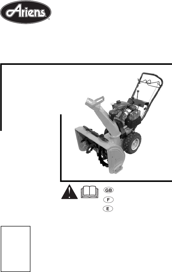
Sno-Thro ® Owner/Operator Manual Models 932037 - 724 932038 - 5520 932039 - 624 932505 - 724 932507 - 520 932508 - 624 U.S. Patents Pending ENGLISH FRANÇAIS ESPAÑOL Transfer model & serial number label from product registration here. Coller l’autocollant du modèle et du numéro de série dans cet encadré. Transferir aquí la etiqueta del modelo y número de serie del registro del producto.
Ariens Company 655 West Ryan Street P.O.
Fred J.
TABLE OF CONTENTS Safety . . . . . . . . . . . . . . . . . . . . . . . . . . . . . . 5 Storage . . . . . . . . . . . . . . . . . . . . . . . . . . . . 26 Assembly . . . . . . . . . . . . . . . . . . . . . . . . . . . 9 Troubleshooting. . . . . . . . . . . . . . . . . . . . . 27 Controls and Features . . . . . . . . . . . . . . . 12 Service Parts . . . . . . . . . . . . . . . . . . . . . . . 27 Operation . . . . . . . . . . . . . . . . . . . . . . . . . . 13 Accessories . . . . . . . . . . . . . . . .
DISCLAIMER Ariens reserves the right to discontinue, make changes to, and add improvements upon its products at any time without public notice or obligation. The descriptions and specifications contained in this manual were in effect at printing. Equipment described within this manual may be optional. Some illustrations may not be applicable to your unit. DELIVERY Customer Note: If you have purchased this product without complete assembly and instruction by your retailer, it is your responsibility to: 1.
REQUIRED OPERATOR TRAINING Original purchaser of this unit was instructed by the seller on safe and proper operation. If unit is to be used by someone other than original purchaser; loaned, rented or sold, ALWAYS provide this manual and any needed safety training before operation. SAFETY DECALS AND LOCATIONS ALWAYS replace missing or damaged Safety Decals. Refer to figure below for Safety Decal locations.
2. DANGER! OS6610 ROTATING PARTS! ONLY use clean-out tool to clear blockages. NEVER use your hands. High speed impeller rotates below discharge opening. Wait for all moving parts to stop before removing clogs or servicing. 3. DANGER! ROTATING PARTS. Keep clear of auger while engine is running. • Read Operator’s Manual. OS2080 • Allow operation only by properly trained adult, never children. • Stop engine and remove ignition key prior to leaving the operator’s position for any reason.
Never direct discharge towards persons or property that may be injured or damaged by thrown objects. Use extreme caution on gravel surfaces. Stay alert for hidden hazards or traffic. Adjust Runners so Scraper Blade does not contact gravel. Abnormal Vibrations are a warning of trouble. Striking a foreign object can damage unit. Immediately stop unit and engine. Remove key and wait for all moving parts to stop. Remove wire from spark plug. Inspect unit and make any necessary repairs before restart.
This product is equipped with an internal combustion type engine. DO NOT use unit on or near any unimproved, forest-covered or brush covered land unless exhaust system is equipped with a spark arrester meeting applicable local, state or federal laws. A spark arrester, if it is used, must be maintained in effective working order by operator. Before tipping unit up onto housing, remove fuel so no spills will occur. Ensure unit is secure and will not tip over during maintenance.
1 1 3 2 2 3 4 1. Discharge Chute 2. Spring Clip 4 3. Chute Crank 4. Pinion Figure 5 1. Wing Knob 2. J-Bolt 3. Lower Handlebar 4. Upper Handlebar Figure 4 932037, 039, 505, 508 932507 OS3000 4 Install Discharge Chute and Chute Crank (932037, 039, 505, 507, 508) (Figure 5, 6, and 7) NOTE: See Figure 5 for the items to install on the unit. 1. Grease chute seat (if not already greased). 2.
932038 3 5 1 1 1. Discharge Chute 2. Retainer Clip 3. Mounting Nut 4. Chute Ring 5. Chute Bracket 6 2 3 4 4 2 OS1921 Figure 7 5 OS4500 Discharge Chute (932038) 1. Grease discharge chute ring if not already greased (Figure 8). 2. Remove mounting hardware from top of engine. 3. Install discharge chute by positioning the chute ring under retainer clip on chute seat. 4. Secure chute support bracket to studs on top of engine with mounting hardware removed in step 2.
CONTROLS AND FEATURES 1 26 2 3 4 5 6 25 7 24 23 22 21 8 10 20 19 9 27 11 18 12 1. Traction Drive Clutch Bail 2. Speed Selector 3. Chute Crank (932037, 039, 505, 507, 508) 4. Muffler Guard (932037, 039, 505, 507, 508) 5. Discharge Chute Deflector 6. Discharge Chute 7. Impeller 8. Auger 9. Auger Gearcase 10. Scraper Blade 11. Oil Fill and Dipstick 12. Gas Tank and Cap 13. Recoil Starter Handle 14. Electric Starter (932037, 038, 039) 15. Primer Bulb 16. Throttle (Engine Stop) 17.
OPERATION Ignition Switch WARNING: AVOID INJURY. Read and understand the entire Safety section before proceeding. Key Switch has two positions: 1. “Stop” - pulled out 2. “Run” - pushed in NOTE: DO NOT twist key after it is inserted. 2 WARNING: To avoid injury to hands and feet, always disengage clutches, shut off engine, and wait for all movement to stop before unclogging or working on snow thrower. Keep hands and feet away from auger and impeller.
2 1 OS1300 1. Choke Closed position: chokes off air to engine for easier start. 2. Choke Open position: allows for normal operation. IMPORTANT: Gradually open choke after engine starts. 1 Throttle 1 2 3 STOP The throttle controls the engine speed. To increase or decrease the engine speed, adjust to: 1. Fast (normal or warm starts) 2. Part-Throttle 3. Slow (cold weather starts) 4.
FILLING FUEL TANK Axle Lock Pin (Figure 10) Wheel Unlocked WARNING: AVOID INJURY. Read and understand the entire Safety section before proceeding. Fuel Shut-Off Valve IMPORTANT: The fuel shut-off valve MUST be in the closed position prior to transporting the unit. The fuel shut-off valve has two positions: • Closed Position: Use this position to service, transport, or store the unit. • Open Position: Use this position to run the unit. Wheel Locked To add fuel to fuel tank: Axle Lock Pin 1.
4. Adjust Runners Check and adjust Runners (see Service and Adjustments). Allow 1/8 in. (3 mm) between scraper blade and hard, smooth surface(s). Allow 1-1/4 in. (30 mm) between scraper blade and uneven or gravel surfaces. 5. Check Engine Fuel & Crankcase Oil WARNING: AVOID INJURY. Read and understand the entire Safety section before proceeding. Check and add fuel if required. Check that the engine crankcase oil is full using dipstick. Refer to Engine Manual for detailed instructions.
Shut Off 1. Release Traction Drive Clutch Bail and allow unit to come to a complete stop. 2. Run Impeller a few minutes after use to prevent freeze-up of Impeller. 3. Release Attachment Clutch Bail and wait for all moving parts to come to a complete stop. 4. Move Throttle to the “Stop” position. 5. Remove key. SNOW REMOVAL IMPORTANT: Allow unit and engine to adjust to the outdoor temperatures before clearing snow. NOTE: Attachment clutch should be engaged before wheel drive clutch when throwing snow. 1.
MAINTENANCE SCHEDULE CHANGE ENGINE OIL The chart below shows the recommended maintenance schedule that should be performed on a regular basis. More frequent service may be required. Change oil after first 2 hours of operation, thereafter change oil every 25 hours (more often if required). Refer to Engine Manual for detailed instructions. Run engine just prior to changing oil. Warm oil will flow more freely and carry away more contamination.
GENERAL LUBRICATION IMPORTANT: Wipe each fitting clean before and after lubrication. IMPORTANT: DO NOT allow grease or oil to get on friction disc, friction plate or belts. NOTE: Apply Stens Mix Hi-Temp Grease or equivalent to the lubrication fittings. See Service Parts. Sno-Thro should be lubricated (Figure 12) at beginning of season or every 25 operating hours. Auger Shaft NOTE: To grease auger shaft, remove shear bolt nuts, and shear bolts. Turn auger on shaft while applying grease at zerk fittings.
SCRAPER BLADE 1 2 3 4 OS0115 1. Pinion 2. Chute Gear 3. Carriage Bolt 4. Spring IMPORTANT: Damage to auger/impeller housing will result if blade wears down too far. Scraper blade is adjustable to compensate for wear. To adjust scraper blade: 1. Tip unit back onto handlebar, support housing and loosen nuts retaining blade. 2. Adjust runners to fully raised position (housing closest to ground). 3. Reposition scraper blade flush with runners and tighten lock nuts.
2. Pull shift rod and adjustment pivot pin out of speed selector lever. 3. Place the speed selector lever in the fastest forward speed position. 4. Pull the shift rod straight down towards the ground as far as it will go. 5. Thread the adjustment pivot pin along the shift rod until it aligns with the mating hole on the speed selector lever. 6. Reinsert the pivot pin into the hole on the speed selector lever. 7. Check forward and reverse speeds. a. Start unit. b.
Replace Attachment Drive Belt 7 4 3 5 6 1 2 1. Housing Bolt Holes 2. Belt Cover 3. Pinion and Gear 4. Spring Clip Pin OS0803 8 5. Chute Crank 6. Chute Strap 7. Chute Strap Mounting Hardware 8. Bottom Cover 1. Place new belt onto lower pulley and while holding brake out of way, tip unit together. 2. Secure blower housing to frame with cap screws. 3. Place belt onto engine sheave. 4. Make sure engine sheave and attachment pulley align.
TRACTION DRIVE BELT REPLACEMENT b.Slide sheave and key to desired position. c. Tighten set screws. 3. Adjust cable slack. IMPORTANT: The clutch cable must be slack when clutch bail is disengaged. a.Center the upper cable adjuster on the mounting bracket, if necessary (Figure 20). NOTE: Housing and frame must be tipped apart and attachment drive belt removed from engine sheave in order to change traction drive belt (Figures 18 and 19).
c. To decrease the distance between the clutch bail and handlebar, move the idler away from the attachment belt. d. Tighten idler adjustment nut. e. Check clutch bail measurement. 6. Check Brake When the clutch bail is disengaged, the brake must contact the attachment belt. When the clutch bail is engaged, the brake must be more than 1/16 in. (1.6 mm) away from the belt (Figure 21). 7. Repeat steps 3–6 until attachment clutch bail distance and brake contact are correct.
FRICTION DISC REPLACEMENT 3 4 6 11 5 1 2 3 4 6 5 5 2 1 9 OS6780 6 7 8 1. Traction Clutch Cable 2. Shift Rod 3. Attachment Control Cable 4. Mounting Nuts 5. Attachment Clutch Arm 6. Speed Selector Arm 7. Cotter Pin and Clevis 8. Traction Drive Clutch Arm 9. Adjustment Barrel Figure 23 10 9 6 1. Hex Shaft 2. Friction Disc 3. Hex Bolts & Nuts 4. Shift Carrier 5. Roll Pins 6. Washers 8 7 7. Bearing Cap Screws 8. Bearing Cap/ Bushing 9. Clutch Fork 10.Large Gear 11.
9. Reinstall one nut to keep the inside bearing cap in place. 10. Remove bearing cap/bushing and washer from right side of unit. 11. Reinstall nuts on screws through side frame to keep screws in place. 12. Slide friction disc assembly and hex shaft to the right until the left end of shaft is clear of left bearing. Tap lightly if necessary, to loosen. The shaft slides out of the small pinion gear and washer. 13. Carefully lift shaft and friction disc out of unit.
SERVICE PARTS ACCESSORIES Order the following parts through your Dealer: Part No. See your authorized Ariens dealer to add the additional accessories available to your Sno-Thro. Description Part No. 00036800 Stens Mix Hi-Temp Grease (3, 3 oz.
TROUBLESHOOTING PROBLEM PROBABLE CAUSE CORRECTION Does not operate in Forward/ Reverse. 1. Friction disc not adjusted properly. 2. Traction belt not functioning. 1. Repair or replace friction disc. See Friction Disc Replacement. 2. Repair or replace traction drive belt. See Traction Drive Belt Replacement. Small rubber beads collect in frame. 1. Friction disc wear. 1. Normal friction disc wear. Chunks or large pieces of rubber mean friction disc should be checked and replaced as necessary.
SPECIFICATIONS Model Number 932037 932038 932039 932505 932507 724 5520 624 724 520 OH195SA LH195SP Power Max - HP (Kw/ 7.0 (5.22) min-1) 5.5 (4.1) Description Engine - Tecumseh 7.0 (5.22) Fast Idle SpeedRPM (min-1) 3600 ± 150 Displacement - in. (cc) 11.88 (195) Electric Start 120V Snow Clearing Width in. (cm) 5.0 (3.73) 6.0 (4.48) Optional 120V or 240V Fuel Tank Capacity - qt. (L) 624 LH195SA OH195SA OH195S 6.0 (4.48) 932508 See Engine Manual 3.5 (3.3) 24 (61.0) 2.0 (1.
3-Year Limited Sno-Thro Warranty Ariens Company 655 West Ryan Street P.O. Box 157 Brillion, WI 54110-0157 920-756-2141 Fax 920-756-2407 www.ariens.
Ariens Company 655 West Ryan Street P.O. Box 157 Brillion, WI 54110-0157 920-756-2141 Fax 920-756-2407 www.ariens.com WARNING The engine exhaust from this product contains chemicals known to the State of California to cause cancer, birth defects or other reproductive harm.