Table of Contents APPROVED FOR RESIDENTIAL APPLIANCES FOR RESIDENTIAL USE ONLY READ AND SAVE THESE INSTRUCTIONS Important Safety Notice .......................................................... 3 Tools and parts ........................................................................ 4 Location Requirements ...................................................... 4 Product Dimensions ........................................................... 4 Venting Requirements .........................................
Tools and Parts Gather the required tools and parts before starting installation. Read and follow the instructions provided with any tools listed here. Tools needed (all models) Location Requirements IMPORTANT: Observe all governing codes and ordinances. Have a qualified technician install the range hood. It is the installer’s responsibility to comply with installation clearances specified on the model/serial rating plate.
Installation Clearances VENTING REQUIREMENTS ■■ Vent system must terminate to the outdoors, except for no vented (recirculating) installations. ■■ Do not terminate the vent system in an attic or other enclosed area. ■■ Do not use a 4” (10.2 cm) laundry-type wall cap. ■■ Use metal vent only. A rigid metal vent is recommended. Plastic or metal foil vent is not recommended. ■■ The length of the vent system and number of elbows should be kept to a minimum to provide efficient performance.
Venting Methods Vent Piece 6” (15.2 cm) This range hood is factory set for venting through the roof or through the wall. You can apply the recirculating venting method by purchasing the Recirculation Kit. The vent system needed for installation is not included. A 6” (15.2 cm) round vent system is recommended. 45° elbow 2.5 ft (0.8 m) 90° elbow 5.0 ft (1.5 m) Roof Venting Wall Venting Recirculating Example Vent System 90° elbow 6 ft (1.8 m) Wall cap 2 ft (0.6 m) Maximum Recommended Length A.
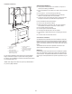
■■ The grounded 3 prong outlet is to be located inside the cabinet above the range hood at a maximum distance of 337⁄16” (85.0 cm) from where the power cord exits the hood. The grounded 3 prong outlet must be accessible after installation of the range hood. See illustration. GROUNDING INSTRUCTIONS ■■ For a grounded, cord-connected range hood: This range hood must be grounded.
Venting Outside Through the Roof Non-Vented (recirculating) Installation Through the Soffit/Cabinet Measure and mark the lines as shown. Use a saber saw or keyhole saw to cut an opening through the top of the cabinet and the roof for the vent. Go to Step 3. B A B* A A G G C B C F D F D I E E H D A. Ceiling B. Vent cover C. Soffit D. 6” (15.2 cm) vent E. Range hood A. Cutout B. 6¼” (15.9 cm)* C. 7¾” (19.7 cm) centerline to cabinet front D. Centerline F. Cabinet G.Wall H. 12” (30.5 cm) min.
Install Range Hood Complete Preparation 3. If not yet attached, install the 6” (15.2 cm) vent transition the top of the range hood liner using two 3.5 x 9.5 mm screws. 4. Locate side mounting bracket flush 1 cm to the bottom of the cabinet side and against the inside of the front cabinet face. Orient the bracket depending on the width of your cabinet as depicted in the diagrams below. Drill ⅛” (3 mm) pilot holes in 6 places, attach a bracket using three 4.
Complete Installation 1. Replace grease filters. See the “Range Hood Care” section. B WARNING C D Electrical Shock Hazard Plug into a grounded 3 prong outlet. Do not remove ground prong. Do not use an adapter. Do not use an extension cord. Failure to follow these instructions can result in death, fire, or electrical shock. A A. Screws - 3.5 x 9.5 mm flat-head (4) B. Face plate (30” x 12” [76.2 cm x 30.5 cm] shown) C. Cabinet (30” x 12” [76.2 cm x 30.5 cm] shown) D. Screws - 4.
Replacing the halogen lamp (ARG628SS models) CAUTION: Before replacing the lamps, disconnect power off to prevent from being switched on accidentally. Turn off the range hood and allow the halogen / incandescent lamp to cool. To avoid damage or decreasing the life of the new bulb, do not touch bulb with bare fingers. Replace bulb, using tissue or wearing cotton gloves to handle bulb. If new lamps do not operate, make sure the lamps are inserted correctly before calling service.
WARRANTY ELICA North America TWO-YEAR LIMITED WARRANTY TO OBTAIN SERVICE UNDER WARRANTY Owner must present proof of original purchase date. Please keep a copy of your dated proof of purchase (sales slip) in order to obtain service under warranty. PARTS AND SERVICE WARRANTY For the period of two (2) year from the date of the original purchase, Elica will provide free of charge, non consumable parts or components that failed due to manufacturing defects.