Quick Start Guide Router AWE-5310 AWE-5510 Arista Networks www.arista.
Headquarters Support Sales 5453 Great America Parkway, +1-408 547-5502 +1-408 547-5501 Santa Clara, CA 95054 USA +1-866 476-0000 +1-866 497-0000 mailto:support@arista.com mailto:support@arista.com +1-408 547-5500 https://www.arista.com/en/ © Copyright 2023 Arista Networks, Inc. All rights reserved. The information contained herein is subject to change without notice.
Contents Contents Chapter 1: Overview................................................................................1 1.1 1.2 1.3 1.4 1.5 1.6 1.7 Scope...................................................................................................................................... 1 Intended Audience..................................................................................................................1 Receiving and Inspecting the Equipment..................................................
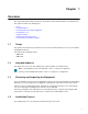
Chapter 1 Overview This Quick Start Guide (QSG) describes the specifications and installation details of the Arista Router. This chapter includes the following topics: • • • • • • • 1.1 Scope Intended Audience Receiving and Inspecting the Equipment Installation Process Safety Information Obtaining Technical Assistance Product and Documentation Updates Scope This guide is intended for properly trained service personnel and technicians in necessary to install the following Arista Router.
1. 2. 3. 4. 5. 1.5 Select and prepare the installation site. Assemble the installation tools listed. Attach the mounting brackets and install the router in an equipment rack. Connect the router to the power source and network devices. Configure the router. Safety Information Refer to the Arista Networks document Safety Information and Translated Safety Warnings available at https://www.arista.com/en/support/product-documentation 1.
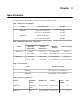
Chapter 2 Specifications This section lists the specifications of Arista Routers described in this guide. Table 1: Dimensions and Weights Router Size (W x H x D) Weight AWE-5310 440 x 43.5 x 430 (mm) 9.3 (kg) 17.32 x 1.71 x 16.92 (inches) 20.5 (lbs) 440 x 88 x 520 (mm) 13.6 (kg) 17.32 x 3.46 x 20.47 (inches) 29.
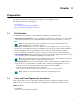
Chapter 3 Preparation This chapter describes the initial setup and preparation for installing the router. This chapter includes the following topics: • • • 3.
3.3 Electrostatic Discharge (ESD) Precautions Observe these guidelines to avoid ESD damage when installing or servicing the router. • • • • • • • 6 Assemble or disassemble equipment only in a static-free work area. Use a conductive work surface (such as an anti-static mat) to dissipate static charge. Wear a conductive wrist strap to dissipate static charge accumulation. Minimize handling of assemblies and components. Keep replacement parts in their original static-free packaging.
Chapter 4 Mounting the Router This chapter provides the instructions to mount the router. This chapter includes the following topics: • • 4.1 Four-Post Rack Mount Two-Post Rack Mount (Optional) Four-Post Rack Mount This section descibes instructions for four-post rack mounting the router. To mount the router in a rack, you need to assemble the mounting brackets to the chassis, then attach the brackets to the rack posts. It includes: • • 4.1.
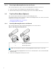
4.1.2 Removing the Mounting Bracket from the Chassis This section describes the steps to remove the mounting brackets from the router chassis. 1. Lift the front edge of the mounting bracket clip with a flathead screwdriver. 2. Slide the bracket away from the front flange (opposite from the installation direction). 4.2 Two-Post Rack Mount (Optional) This section describes instructions for two-post rack mounting the router.
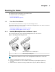
Mounting the Router 4.2.2 Inserting the Router into the Rack This section describes the steps to insert the router into the rack. Figure 3: Inserting the Router into the Rack 1 Screws attaching chassis securely to rack 2 Screws attaching chassis securely to rack Note: For thermal purposes, make sure that there is 1RU clearance above the rack mount bracket. 1. 2. 3. 4. Lift the chassis, attached with brackets, into the rack.
Chapter 5 LED Status Indicators This section describes the front panel LED status of the device. Table 5: LED Status Indicators LED Name System Status LED LED State Device Status Off No power or in the midst of a power cycle. Blinking Green System is powering up. Green The system is operating in a normal initialization sequence. Normal operations. Blue The locator function is active. Amber System is malfunctioning.
Chapter 6 Parts List Each router provides an accessory kit that contains parts that are required to install the router. This section lists the installation parts contained in the router accessory kit.
Table 6: SKU and Product Details SKU AWE-5310 Product Description Arista 5310, 4x10G/1G RJ45, 4x10G/1G SFP+ router, front to rear air, 48W AC Arista 5310, 4x RJ45 (w/2x Fail to Wire) 4x10G SFP+, 2 NIM slots, front to rear air, 2 550W AC AWE-5510 14 Arista 5510, 8x SFP+ 10G, 8x SFP+ 10G Enhanced, 4 NIM slots, front to rear air, 2 800W AC
Chapter 7 Front Panel This section describes the front panel of each router. 7.1 AWE-5310 The AWE-5310 front panel includes the following key components: Figure 4: AWE-5310 Front Panel 1 System status LEDs 2 USB port Type-A 3 LCD Panel 4 LCD Upper Button 5 LCD Lower Button 6 SMA Connector 7 2xLFF OCP NIC 3.
7.2 AWE-5510 The AWE-5510 front panel includes the following key components: Figure 5: AWE-5510 Front Panel 16 1 System status LEDs 2 USB port Type-A 3 LCD Panel 4 LCD Upper Button 5 LCD Lower Button 6 4xLFF OCP NIC 3.
Chapter 8 Rear Panel The section describes the rear panel of each router. 8.
8.
Chapter 9 Regulatory Model Numbers This section lists the Regulatory Model Numbers (RMNs) of the routers described in this document.
Appendix A EMC Class A Notices and Warnings Refer to the following sections for detailed EMC Class A Notices and Warnings. Traditional Chinese Class A EMC Statement (Taiwan) Federal Communication Commission Interference Statement Federal Communication Commission Interference StatementThis device complies with Part 15 of the FCC Rules.
Radiation Exposure Statement:This equipment complies with ISED radiation exposure limits set forth for an uncontrolled environment. This equipment should be installed and operated with greater than 20cm between the radiator & your body. Déclaration d'exposition aux radiations:Cet équipement est conforme aux limites d'exposition aux rayonnements ISED établies pour un environnement non contrôlé. Cet équipement doit être installé et utilisé à plus de 20cm entre le radiateur et votre corps.
EMC Class A Notices and Warnings Warning: Operation of this equipment in a residential environment could cause radio interference. This device complies with Directive 2014/53/EU and UK Radio Equipment Regulations 2017 SI 2017/1206. issued by the Commission of the European Community. - Declaration of Conformity Please added certification standard in your user manual which depended on the test standards your device performed.