
Installation Instructions
17
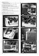
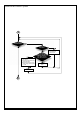
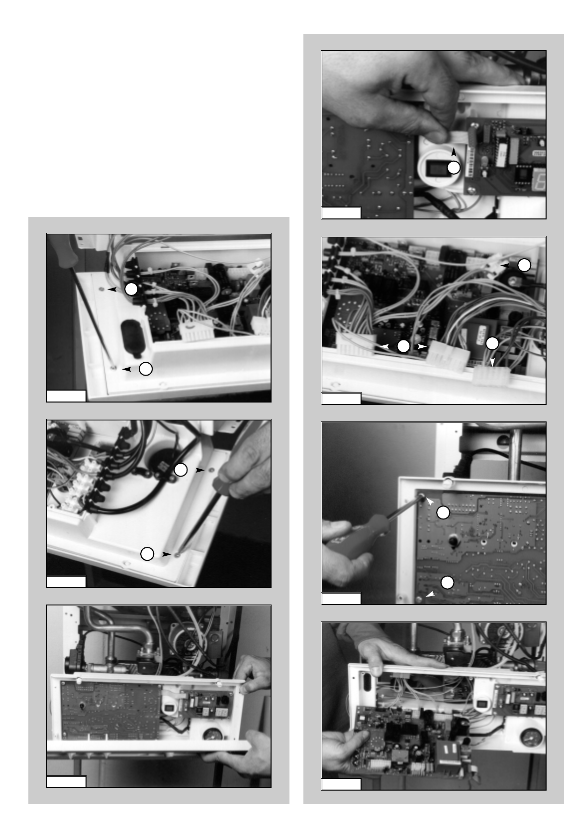
Removing the P.C.B.s
1. Remove the inspection cover on the reverse of the
control panel (F
IG. 1.60);
2. Remove the screws “S1” (FIG. 1.65 & FIG. 1.66);
3. Remove the facia panel (FIG. 1.67);
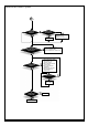
5. Disconnect the connection cable ”T1” (F
IG. 1.68);
6. Unplug the electrical connectors “U1” from the main
P.C.B. (Fig. 1.69);
7. Remove the main P.C.B. mounting screws “V1’ (four in
total) (F
IG. 1.70);
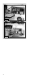
8. Remove the main P.C.B. (FIG. 1.71);
9. Remove the display P.C.B. mounting screws “W1’ (F
IG.
1.72);
10.Remove the display P.C.B. (F
IG. 1.73);
11.Replace either P.C.B. in reverse order.
FIG. 1.67
S1
FIG. 1.65
FIG. 1.66
S1
FIG. 1.70
T1
FIG. 1.68
FIG. 1.69
U1
S1
S1
U1
U1
V1
V1
FIG. 1.71