SERIES Installation and Servicing Instructions Type C Boilers ACO 27 MFFI G.C.N: ACO 32 MFFI G.C.N: ACO 27 RFFI G.C.N: ACO 32 RFFI G.C.
TABLE OF CONTENTS 1. GENERAL INFORMATION TECHNICAL INFORMATION OVERALL VIEW PAGE 6. GENERAL INFORMATION 1.1. 1.2. 1.3. 2. PAGE 3 4 6 MAINTENANCE 52 6.1. 6.2. 6.3. 6.4. 52 52 52 52 GENERAL REMARKS CLEANING THE PRIMARY EXCHANGER CLEANING THE CONDENSATE TRAP OPERATIONAL TEST INSTALLATION 2.1. 2.2. 2.3. 2.4. 2.5. 2.6. 2.7. 2.8. 2.9. 2.9.1 2.9.2 2.9.3 2.9.4 2.10. 2.11. 2.11.1. 2.12. 2.13. 2.14.
1. GENERAL INFORMATION 1.1. This manual is an integral and essential part of the product. It should be kept with the appliance so that it can be consulted by the user and our authorised personnel. Read the instructions and recommendations in these Installation and Servicing Instructions carefully to ensure proper installation, use and maintenance of the appliance.
General Info Name CE Certification Flue Type Energy Performance Heat Input max (Domestic Hot Water) Heat Input max/min (Central Heating) Heat Output max (Domestic Hot Water) Heat Output max/min (Central Heating) Efficiency of Nominal Heat Input (60/80°C) Efficiency of Nominal Heat Input (30/50°C) Efficiency at 30% of Nominal Heat Input (47°C) Efficiency at 30% of Nominal Heat Input (30°C) Efficiency at Minimum Input Efficiency (Dir.
General Info Name CE Certification Flue Type Energy Performance Heat Input max (Domestic Hot Water) Heat Input max/min (Central Heating) Heat Output max (Domestic Hot Water) Heat Output max/min (Central Heating) Efficiency of Nominal Heat Input (60/80°C) Efficiency of Nominal Heat Input (30/50°C) Efficiency at 30% of Nominal Heat Input (47°C) Efficiency at 30% of Nominal Heat Input (30°C) Efficiency at Minimum Input Efficiency (Dir.
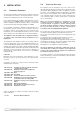
1.3. OVERALL VIEW 27/32 RFFI (SYSTEM) 27/32 MFFI (COMBI) 1 26 1 26 2 3 25 2 3 25 4 5 4 5 6 7 8 6 7 8 24 24 9 9 23 23 22 22 21 20 10 20 11 19 19 18 18 12 13 14 15 16 17 10 12 14 15 16 17 FIG. 1.0 LEGEND: 1. Flue connector 2. Mixer 3. Fan 4. Spark generator 5. Burner 6. Ignition and detection electrode 7. Air release valve 8. Main heat exchanger (aluminium) 9. Central Heating flow temperature probe 10. Automatic by-pass 11. Domestic Hot Water temperature probe 12.
2. INSTALLATION 2.1. REFERENCE STANDARDS The technical information and instructions provided herein below are intended for the installer / Servicing Technician so that the unit may be installed and serviced correctly and safely. In the United Kingdom the installation and initial start up of the boiler must be by a CORGI Registered Installer in accordance with the installation standards currently in effect, as well as with any and all local health and safety standards i.e. CORGI.
2.3. OVERALL DIMENSIONS 27/32 RFFI (SYSTEM) 785 FIG. 2.1 280 450 FIG. 2.0 2.4.
2.5. MOUNTING THE APPLIANCE After removing the boiler from its packaging, remove the template from the separate box containing the connection kit. NOTE: Pay particular attention to any test water that may spill from the appliance. Place the template in the position the appliance is to be mounted and after ensuring it is hanging squarely, use it to mark the holes for the hanging bracket, connection kit and flue pipe(s) NB: For further information relating to the flue installation please refer to Section 2.
2.8. WATER CONNECTIONS VIEW OF THE BOILER CONNECTIONS Legend: 27/32 MFFI (COMBI) A B C D E H I J I B A C D J E H 27/32 RFFI (SYSTEM) I C A J E H FIG. 2.
The discharge pipe must be terminated in a suitable position: i) Connecting in to an internal soil stack (at least 450 mm above the invert of the stack). A trap giving a water seal of at least 75 mm must be incorporated into the pipe run, there also must be an air break upstream of the trap. ii) Connecting into the waste system of the building such as a washing machine or sink trap.
2. External termination of condensate drainage pipe via internal discharge branch (e.g. sink waste) and condensate siphon WATER TREATMENT The boiler is equipped with an aluminium alloy main heat exchanger.
2.9. CONNECTING THE FLUE IMPORTANT!! BEFORE CONNECTING THE FLUE, ENSURE THAT 1 LITRE OF WATER HAS BEEN POURED INTO THE EXHAUST CONNECTION TO FILL THE CONDENSATE TRAP (FIG.2.7). SHOULD THE TRAP BE EMPTY THERE IS A TEMPORARY RISK OF FLUE GASSES ESCAPING INTO THE ROOM. FLUE SYSTEM The provision for satisfactory flue termination must be made as described in BS 5440-1. The appliance must be installed so that the flue terminal is exposed to outdoor air.
Warning The exhaust gas ducts must not be in contact with or close to inflammable material and must not pass through building structures or walls made of inflammable material. When replacing an old appliance, the flue system must be changed. Important Ensure that the flue is not blocked. Ensure that the flue is supported and assembled in accordance with these instructions. Level 118 Installation without extension Fig. 2.10 Level Installation with extension Fig. 2.11 2.9.
Clamp Screws Seal Fig. 2.12 Should the flue require extending, the flue connections are push fit, however, one flue bracket should be used to secure each metre of flue. 2.9.2 FITTING THE 5” FLUE (Ø 80 / 125 HORIZONTAL/VERTICAL) NOTE: SEE PAGE 19 FOR MAXIMUM AND MINIMUM FLUE RUNS. Once the boiler has been positioned on the wall, it is necessary to insert the Ø80/125 adaptor (FIG. 2.13) for both horizontal and vertical flue runs into the boiler flue socket (not supplied with flue kit - Part No 3318095).
NOTE: SEE PAGE 19 FOR MAXIMUM AND MINIMUM FLUE RUNS. 2.9.3. FITTING THE COAXIAL FLUE (Ø 60 / 100 VERTICAL) CONTENTS: 1X SILICONE O-RING (60mm) 1X CONICAL ADAPTOR (60/100mm) 1X VERTICAL FLUE KIT (80/125mm) 3X SCREWS The vertical flue kit is supplied with a specially designed weather proof terminal fitted, it can be used either with a flat roof or a pitched roof. The Vertical flue kits useable lengths with the pitched roof flashings are indicated in Fig. 2.16.
2.9.4. FITTING THE TWIN PIPE (Ø80 / 80) NOTE: SEE PAGE 19 FOR MAXIMUM AND MINIMUM FLUE RUNS. Where it is not possible to terminate the flue within the distance permitted for coaxial flues, the twin flue pipe can be used by fitting a special adaptor to the flue connector and using the aperture for the air intake located on top of the combustion chamber. Always ensure that the flue is adequately supported, using one flue bracket per extension and avoiding low points. (MTS supply suitable clamps as Part No.
Fig. 2.18 ø 100 In the event that the air intake and exhaust are run to the left, it will be necessary to reduce the height of the air intake by cutting 20mm from the base of the air intake elbow (see Fig. 2.
For coaxial systems, the maximum development value, mentioned in the table below also takes into account an elbow. For twin flue systems the maximum development value, mentioned in the table includes the exhaust gas/air intake terminal. Type 5 outlets should respect the following instructions: 1- Use the same ø 80 mm flue pipes for the air intakes and exhaust gas ducts.
TYPE 1 TYPE 4 TYPE 2 TYPE 3 TYPE 5 Fig. 2.21 NOTE: DRAWINGS ARE INDICATIVE OF FLUEING OPTIONS ONLY. 2.10. FITTING THE MECHANICAL / DIGITAL CLOCK The ACO MFFI (Combi) boiler is supplied with a factory fitted mechanical time clock. There is a digital clock available as an optional extra (code: 706348). To fit the digital clock it is necessary to proceed as follows:1. Remove the outer casing 2. Open the control panel (see Section 2.22); C2 C2 C2 FIG. 2.22 3.
The ACO RFFI (System) boiler is not supplied with a clock, however a mechanical and digital clock is available as an optional extra (mechanical - code: 706349 and digital - code: 706348) To fit the clock it is necessary to proceed as follows:1. Remove the outer casing 2. Open the control panel (see Section 2.22); 3. Unplug the electrical connection from the PCB and unscrew the four screws (Fig. 2.26); 4. Remove the time clock (Fig. 2.27). FIG. 2.23 5.
2.11. SETTING THE MECHANICAL TIME CLOCK 1. General layout The mechanical clock covers a 24 hour period. Each tappet represents 15 minutes A (Fig. 2.30). An override switch is located on the clock B (Fig 2.30). 2. To set the time To set the time of day, grasp the outer edge of the dial and turn slowly clockwise until the correct time is lined up with the arrow C (Fig. 2.30). 3. To Set the "On" and "Off" times The clock uses a 24hours system. e.g. 8 = 8.00 am and 18 = 6.00 pm.
Automatic Operation Manual Operation Continuous Operation = ON = ON = Continuously ON = OFF = OFF = Continuously OFF The switching times correspond to the program entered. If the current switching mode is changed manually, the next switching time will be carried out automatically again according to the entered switching program. You can only return to automatic mode from the continuously-ON and continuouslyOFF switching modes by pressing the " " key.
2.12. ACCESSORY CONNECTION IMPORTANT!! Before carrying out any repairs to the appliance always ensure that the external power supply has been isolated. The boiler will remain live even when the ON/OFF knob is in the “O”(off) position. In order to gain access to the external control connections, it is first necessary to remove the casing (as shown in Section 3.2) then proceed as follows: 1. Remove the cover of the main PCB box (Fig 2.31). 2.
FITTING THE EXTERNAL SENSOR The exter nal sensor is supplied with the interface PCB (Fig. 2.33). The external sensor should be sited no more than 50 m from the boiler and on an external north facing wall, between 2 and 2.5 metres above the ground. It should also be ensured that the external sensor is positioned out of direct sunlight. To connect the external sensor, plug the interface PCB into connector CN6 on the main PCB (see Fig. 2.33).
CN4 CN1 CN3 N VG CN2 CN5 7 8 9 10 1112 CI AC CN12 CN1 WFS 1 CN8 CN11 FUSE NTC1 NTC2 FS CN10 7 8 9 10 1112 CN6 CN9 NTC3 PA CN7 CN12 O P CN8 Day CN11 h MV CN5 L CN16 N 1 L 2 12 11 10 9 8 7 6 5 4 3 2 1 1 2 Nr Mr Rs Bn Az 2 Bl Mr 1 Rs Nr Mr Bl R/N Mr Bl Nr Nr 1 4 TIMER 1 Bl Bl 1 Gr Gr Bn Bn Gr 1 Bn Bn 2 3 FIG. 2.
Legend: A B C D E F H I K L M N O P - ON/OFF button Green LED (Indicates burner on) COMFORT button Programming key + Central Heating temperature adjustment Menu button Programming key Domestic Hot Water temperature adjustment (MFFI only) Comfort function LED (yellow) (MFFI only) Red LED (indicates lockout) Multifunction display Reset button EEPROM key Interface PCB (optional) FS NTC1 NTC2 NTC3 OP VG M CI MV AC PA TA TS CR* SE* - Domestic hot water flow switch Central Heating flow temperature probe Cent
2.14. WATER CIRCUIT DIAGRAM 27/32 MFFI (Combi) 20 1 2 3 4 5 6 19 18 7 8 9 17 16 10 15 14 11 12 13 FIG. 2.
27/32 RFFI (System) FIG. 2.
3. COMMISSIONING 3.1. INITIAL PREPARATION Manual Air Vent initiative. In Sections 11 MTS (GB) Limited support the and 12 of this manual you will find the commissioning checklist (page 78) and the service interval record (Page 79), It is important the commissioning checklist is completed in the presence of your customer, they are shown how to use it, and it is signed by them. Please instruct your customer that they must have this manual with them whenever they contact a service engineer or us.
off and flush through cold, fill the central heating system again, add a flushing detergent, we highly recommend the use of a flushing detergent appropriate for the metals used in the aluminium alloy circuit.
3.2. REMOVING THE CASING A To remove the front casing panel, follow these steps: 1. Remove the screws “A” (FIG 3.1); 2. Remove the four screws from case hooks (two at the top and two at the bottom) and rotate anti-clockwise (FIG 3.2); 3. Lift and unhook the case panel (FIG 3.3). A FIG. 3.2 FIG. 3.1 FIG. 3.
3.3. CONTROL PANEL 27/32 MFFI (Combi) I A H G B F C E D FIG. 3.4 Button Description Description ON/OFF Switch A Green LED (illuminated = burner on) “COMFORT” Function Push-button B Time clock C Selector knob for Summer/Winter Central Heating Temperature Adjustment Knob D Control Panel Cover E Domestic Hot Water Temperature Adjustment Knob F Heating System Pressure Gauge G “COMFORT” Function L.E.
27/32 RFFI (System) I A H G B F C D FIG. 3.4 Button Description Description ON/OFF Switch Not used Reset Button/ Flue Test**/ scroll through Functions Menu Menu Switch A Green LED (illuminated = burner on) B Time clock (Optional Extra) C Central Heating Temperature Adjustment Knob D Control Panel Cover F Heating System Pressure Gauge G Heating only L.E.
3.4. INITIAL START-UP H C FIG. 3.5 1. Make sure that: - the cap of the automatic air release valve is loosened; - the system pressure is at least 1 bar on the pressure gauge “F” (Fig. 3.4); - the gas cock is closed (Fig. 3.7); - the electrical connection has been carried out in the correct manner. To allow the air to escape from the system, FIG. 3.7 proceed as follows: - push the On/off button and turn the knob “C” (Fig. 3.5) to the “winter” position.
3.5.
3.6. OPERATING PARAMETERS The boiler has been designed to allow easy use of the operating parameters. 3.6.1 REGULATION MENU TABLE Summary of the functions accessed when the RESET button and the menu button are pushed at the same time for 5 seconds. On the display will appear the parameters indicated on table 3A. To switch between the different parameters press the button. To modify the parameters push the programming keys and Fig. 3.10 .
left-hand display right-hand display r from00 to 01 p from90 to 91 p6 from-20 to +20 Correction of heat curve translation P5 from 0_3 to 3_0 Curve incline t A Function selects low temperature systems or standard systems Temperature regulation controlled by external sensor factory setting 01 Standard 00 Low Temperature 90 Test Function 81 Bus Address (Do not modify) b0 Set-point second heating zone b1 GSM value (Do not modify) b 20 NOT USED b 30 NOT USED b 40 NOT USED b 50 NO
Maximum Heating Power adjustment 2 The maximum heating power can be adjusted between the maximum power allowed by the boiler (22.5kW - ACO 27 and 28kW - ACO 32) and the minimum recommended power (10kW - ACO 27 and 13kW - ACO 32) indicated in the graph below (Parameter 2 = 20%). The value is factory set to 70% of the maximum power. The value set (expressed as a percentage) can be displayed and modified as illustrated in Section 3.6.1 (parameter 2).
Boiler types F Factory setting: 00 - ACO 27 / 32 MFFI (COMBI) 02 - ACO 27 / 32 RFFI (SYSTEM) THIS PARAMETER MUST NEVER BE ADJUSTED. Secondary outlet Function E (This parameter can be modified only with the interface PCB connected) With the interface PCB connected, it is possible to set the boiler to operate with one of the following accessories, (see Section 2.12 for further information). The setting can be varied by pushing the and keys, the following options are available: 00 01 02 03 FIG. 3.
SETTING THE TEMPERATURE FIELD r Using the programming keys and it is possible to make the following adjustments: 00” signifies that the flow temperature (which may be set by “0 means of the knob on the front control panel) may be regulated from 20 to 75°C. 01” signifies that the flow temperature (which also may be set by “0 means of the knob on the front control panel) may be regulated from 46 to 82 °C. FIG. 3.
SETTING THE CURVE INCLINE P 5 (Only enabled when an outdoor sensor is installed) When using an outdoor sensor, the microprocessor-controlled P.C.B. calculates the most suitable flow temperature, taking into account the exter nal temperature and the type of system. The microprocessor is capable of doing this because it is possible to establish a link between the external temperature and the flow temperature of the Central Heating system water. This link translates into a "thermal curve".
to press the and keys together, two dashes appear at the top of the right-hand display (see Fig. 3.29). This function is disabled by pressing the reset key . b - by pressing the key, the boiler is forced to operate at minimum power, two dashes appear at the bottom of the righthand display (Fig. 3.31). This function is disabled by pressing the reset key. max power DHW 3.6.2 SETTINGS DISPLAY FIG. 3.
3.6.3 GAS REGULATION CHECK Supply pressure check 1. Loosen screw “1” (Fig. 3.33) and connect the pressure gauge connection pipe into the test point. 2. Turn the boiler on at maximum power, enabling the “flue sweep” function (press the key for 5 seconds and then press the programming keys and together ensuring the dashes are at the top of the display (see Fig. 3.30). The supply pressure should correspond to that shown for the type of gas the boiler is designed for methane gas G20 (see table below). 3.
3.6.4 IGNITION DELAY ADJUSTMENT The ignition delay can be adjusted to between 0 and 7 minutes. The delay is factory set to 2 minutes. The value set can be displayed and modified as illustrated in paragraph 3.6.1 (parameter 3). 3.6.5 ADJUSTING THE MAXIMUM HEATING POWER The maximum heating power can be adjusted between the maximum power allowed by the boiler (22.5kW - ACO 27 and 28kW - ACO 32) and the minimum recommended power (10kW - ACO 27 and 13kW - ACO 32) indicated in the graph (parameter 2 = 20).
3.10 BOILER SAFETY SYSTEMS The boiler is protected from malfunctioning by means of internal checks by the P.C.B., which brings the boiler to a stop if necessary. In the event of the boiler being shut off in this manner, a code appears on the display which refers to the type of shut-off and the reason behind it.
DAILY TEST. In order to prevent sticking components, the boiler carries out a selfdiagnosing test every 21 hours: the pump runs for 15 seconds and the diverter valve moves once. ANTI-FROST DEVICE. The anti-frost function acts on the central heating flow temperature probe, independently from other regulations, when the electrical supply is turned on. If the primary circuit temperature falls below 8°C the pump will run for 2 minutes.
4. ZONE VALVES The boiler can be connected to a central heating system that uses two zone valves allow connection to an indirect storage cylinder. There are two possible types of wiring diagram, one for the connection to an Unvented Cylinder (Diagram. A, page 49) and one for connection to an open vented cylinder (Diagram B, page 50). In both cases the boiler connection is shown as TA, which relates to the terminal on the PCB for external controls (see FIG. 4.2).
WIRING DIAGRAM FOR CONNECTION TO AN ARISTON UNVENTED CYLINDER DIAGRAM A 49
WIRING DIAGRAM FOR CONNECTION TO AN OPEN VENTED CYLINDER 50 DIAGRAM B
5. SEQUENCE OF OPERATION 5.1 CENTRAL HEATING MODE Activation of the time clock and/or room thermostat starts the boiler. The letter C is shown in the display followed by the flow temperature. With the boiler in rest, the diverter valve is in the domestic hot water position, activation of the central heating changes the position of the motorised valve head, moving the diverter valve into the central heating position.
6. MAINTENANCE 6.1. To ensure the validity of the 5 Year Guarantee, the boiler must be serviced annually by a CORGI registered gas engineer. GENERAL REMARKS Provided the boiler was registered within the terms stated on the guarantee card, MTS (GB) Limited will write to the householder as the boiler becomes due for it’s annual service.
7. To ensure efficient safe operation, the boiler must be serviced annually by a competent person. SERVICING INSTRUCTIONS Before starting any servicing work, ensure both the gas and electrical supplies to the boiler are isolated and the boiler is cool. Before and after servicing, a combustion analysis should be made via the flue sampling point (please refer to 3.6.3). After servicing, preliminary electrical system checks must be carried out to ensure electrical safety (i.e.
FIG. 7.4 7.3. ACCESS TO THE COMBUSTION CHAMBER 7.3.1. REMOVING THE FAN 1. Disconnect the electrical connector “C” (FIG. 7.5); 2. Disconnect the compensation tube “D” (FIG. 7.5); 3. Remove the clip “E” (FIG. 7.6). 4. Unscrew the four screws “F” (FIG. 7.7); 5. Remove the fan (FIG. 7.8). FIG. 7.5 D C FIG. 7.6 E FIG. 7.7 F F F FIG. 7.
7.3.2. REMOVING THE AIR PRESSURE SWITCH 7.3.3. REMOVING THE BURNER 1. Disconnect the electrical connector “G” (FIG. 7.9); 2. Disconnect the compensation tube “H” (FIG. 7.9); 3. Unscrew the two screws “I” (FIG. 7.10); 4. Remove the Air Pressure Switch With the fan removed (see Section 7.3.1); 1. Remove the four allen screws “J” (FIG. 7.11); 2. Slide the burner from its housing (FIG. 7.12 - 7.13). FIG. 7.9 FIG. 7.11 H G J FIG. 7.10 FIG. 7.12 I I FIG. 7.
7.3.4. REMOVING THE ELECTRODES 7.3.5. REMOVING THE HEAT EXCHANGER 1. Remove the two allen screws “K”, pulling off the ignition cable (FIG. 7.14); 3. Extract the electrodes (FIG. 7.15). FIG. 7.14 IMPORTANT!! Every time that the combustion chamber cover or the primary heat exchanger is removed from the boiler, the combustion chamber seal must be checked and where necessary replaced (code: 65102217).
FIG. 7.18 FIG. 7.22 FIG. 7.19 FIG. 7.23 O FIG. 7.20 FIG. 7.24 FIG. 7.
7.3.6. REMOVING THE CONDENSATE TRAP (TUBE) 7.3.7. REMOVING THE CONDENSATE TRAP 1. Open the clamp “Q” and remove the condensate trap connection pipe (FIG. 7.25); 2. Unscrew the screw “R” (FIG. 7.26); 3. Remove the condensate tube. 1. 2. 3. 4. FIG. 7.25 NOTE: Take care when removing the blanking cap to place a container under the boiler as this will release the contents of the condensate trap. Remove the condensate trap tube (see section 7.3.6); Unscrew the screw “S” (FIG. 7.
7.4 ACCESS TO THE GAS VALVE 7.4.1. REMOVING THE GAS VALVE 1. Remove the casing and lower the control panel as instructed in Section 7.1. 2. Press the release button “U” for the control panel (Fig. 7.29) and pull forward to remove from the boiler frame. 3. Clip the control panel onto the frame of the boiler. (Fig. 7.30). FIG. 7.29 1. Disconnect the electrical connection “V” from the gas valve (FIG. 7.31); 2. Release the top nut “W” (FIG. 7.31); 3.
7.4.2. REMOVING THE SPARK GENERATOR 7.5 ACCESS TO THE WATER CIRCUIT 1. Disconnect the electrical connection “Y” from the spark generator (FIG. 7.34); 2. Remove the screws “Z” from the bottom of the spark generator (FIG. 7.35); 4. Remove the spark generator. Important! Before any component is removed, the boiler must be drained of all water. 7.5.1. REMOVING THE D.H.W. (SECONDARY) EXCHANGER (MFFI ONLY) 1. Remove the two allen screws “A1” (FIG. 7.36); 2.
7.5.2. REMOVING THE SAFETY VALVE 7.5.3. REMOVING THE AUTOMATIC AIR VENT 1. Remove the U-clip “A2” (Fig. 7.39); 2. Remove the valve (Fig. 7.40). 1. Remove the U-clip “A3” (FIG. 7.41); 2. Unscrew valve (FIG. 7.42); 3. Remove (FIG. 7.43). A3 A2 FIG. 7.41 FIG. 7.39 FIG. 7.42 FIG. 7.43 FIG. 7.
7.5.4. REMOVING THE DIVERTER VALVE ACTUATOR 1. Unplug the electrical connector “A4” (FIG. 7.44); 2. Release the retaining clip “A5” and remove the diverter valve actuator (FIG. 7.45). FIG. 7.47 A4 7.5.6. REMOVING THE PUMP 1. Unplug the electrical connection “A7” (FIG. 7.48); 2. Unscrew the four screws “A8” (FIG. 7.49); 3. Remove the pump (FIG. 7.50). FIG. 7.44 A7 A5 FIG. 7.48 FIG. 7.45 7.5.5. REMOVING THE D.H.W. FLOW SWITCH (MFFI ONLY) 1. Unplug the electrical connector; 2.
7.5.7. REMOVING THE PRESSURE GAUGE 1. Release U-clip “B1” (FIG. 7.51 - 7.52); 2. Ease the pressure gauge through the control panel from the rear; 3. Remove the pressure gauge. (FIG 7.53). B1 FIG. 7.50 FIG. 7.51 FIG. 7.52 FIG. 7.
7.5.8. REMOVING THE EXPANSION VESSEL 1. 2. 3. 3. Unscrew the screws “B2” (FIG. 7.54); Loosen nut “B3” (FIG. 7.55); Unscrew the screw “B4” (FIG. 7.56); Remove the expansion vessel (FIG. 7.57). B2 FIG. 7.54 FIG. 7.57 7.5.9 REMOVING (MFFI ONLY) B3 THE D.H.W. TEMPERATURE PROBE (N.T.C.) 1. Remove the electrical connector “B5” by pulling off (Fig. 7.58); 2. Unscrew and remove the D.H.W. temperature probe “B6” (FIG. 7.59). FIG. 7.55 B5 B4 FIG. 7.58 FIG. 7.56 B6 FIG. 7.
7.5.10. Removing the C.H. Flow Temperature Probe (N.T.C.) 7.5.11. REMOVING THE C.H. RETURN TEMPERATURE PROBE (N.T.C.) 1. Unscrew the two screws “B7” (Fig. 7.60); 2. Remove the electrical connection from the C.H. flow temperature probe (FIG. 7.61). 1. Unscrew the two screws “B8” (Fig. 7.62); 2. Remove the electrical connection from the C.H. flow temperature probe (FIG. 7.63). B8 B7 FIG. 7.60 FIG. 7.62 FIG. 7.61 FIG. 7.
7.6 ACCESS TO THE CONTROL SYSTEM 7.6.1. CHECKING THE FUSES 1. Remove the inspection cover of the PCB box (FIG . 7.64); 2. Remove the fuses by pushing and rotating fuse holders “B9” (FIG. 7.65). 7.6.2. REMOVING THE P.C.B.S 1. Remove the inspection cover of the PCB box (FIG. 7.66); 2. Unplug all the electrical connections (FIG. 7.67); 3. Unscrew the screws “C1” (FIG. 7.67); 4. Pull forward the main PCB (FIG. 7.68); 5. Unscrew the screws “C2” (Fig. 7.69); 6. Remove the cover of the control panel (FIG. 7.
7.6.3. REMOVING THE TIME CLOCK C2 1. Open the control panel (see the paragraph “Removing the P.C.B.s”); 2. Unplug the electrical connection from the time clock and unscrew the four screws (FIG. 7.73); 3. Remove the time clock (FIG. 7.74). C2 C2 FIG. 7.69 FIG. 7.73 FIG. 7.70 C3 C3 C4 C3 C3 FIG. 7.71 FIG. 7.74 FIG. 7.
8. FAULT FINDING 8.1. FAULT FINDING GUIDE (FLOW-CHARTS) It is possible to detect and correct defects by using the standard fault finding diagrams described in this chapter.
Model 27/32 RFFI SYSTEM 69
9.
Key no. 1 10 14 18 18 21 29 31 32 35 37 42 46 54 55 75 90 91 101 107 107 125 129 131 135 135 203 204 215 216 109 G.C. part no. Description Flue restrictor Spark generator Main P.C.B.
27/32 RFFI (SYSTEM) 59 58 4 1 2 3 4 5 5 60 6 7 8 56 55 54 53 57 6 61 62 51 50 57 119 120 121 118 63 9 52 122 117 10 11 116 115 64 123 114 112 12 65 109 110 108 105 106 111 113 111 107 108 107 49 RESET ON/OFF 8 7 6 62 61 103 68 13 72 99 73 48 93 94 74 71 14 94 98 70 69 102 101 100 6 66 67 104 95 97 85 29 86 75 92 77 78 91 29 76 15 47 96 16 46 45 17 18 90 85 29 44 46 79 80 45 43 89 84 81 33 34 86 19 42 20 22 23 24 25 26 27
Key no. 1 10 14 26 28 31 39 43 52 53 74 89 88 93 93 115 118 120 123 123 216 217 98 G.C. part no. Description Flue restrictor Spark generator Main P.C.B. Safety valve (3bar) Pressure gauge Gas valve Pump Automatic air vent Expansion vessel Air pressure switch Hose clip Retaining clip (NTC CH) NTC (CH) Main exchanger (27 KW) Main exchanger (32 KW) Ignition electrode Detection electrode Fan Burner (27kW) Burner (32kW) Display P.C.B. Cable (Display P.C.B.) Combustion Chamber Seal and Grease ARISTON Part. No.
10. ANNUAL MAINTENANCE CHECKLIST To ensure that the five year guarantee applies, the following checks must be carried out once a year and the service history completed in the Service Interval Record (Section 12, page 79) by a CORGI registered engineer: 1. Visually check the appliance for correct installation; 2. Check the appliance for the correct operation; 3. Check the flue and flue installation for correct siting, installation and that it is in good condition.; 4.
11.
12.
A charge will be made to the owner of the appliance if: ∑ ∑ ∑ ∑ The reason for any service visit is as a direct result of a failure to install the appliance in accordance with the manufacturer’s instructions. Your installer does not complete the necessary commissioning process and procedure as detailed in the Installation and Operating Instructions. Your appliance is not serviced on or before the 12 month anniversary of installation - this only applies to appliances with a 2 and 5 year guarantee.