
Technical information


42
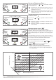
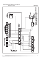
Test Function
tt
The test function is used to enable the engineer/installer to check
the combustion rate (see Section 3.6.3).
The P
.C
.B
.
allows the boiler to be forced to the maximum or
minimum power. Enable the test function, two dashes will appear on
the r
ight-hand displa
y (see Fig.
3.29).
To select operation at maximum power, press the programming key
, two dashes will appear at the top of the right-hand display (see
Fig.
3.30).
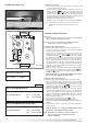
This function is disabled when you press reset key to quit the
adjustments men
u.
To select operation at minimum power, press the programming key
, two dashes will appear at the bottom of the right-hand display
(see Fig.
3.30).
This function is disab
led when y
ou press reset key
“H” to quit the adjustments menu.
Note: The boiler can be forced to the maximum and minimum power
e
v
en without enab
ling the test function via the adjustments
menu:
a - b
y pressing the Reset k
e
y
for 5 seconds, the boiler is
automatically forced to test mode and t-- will be displayed, the
boiler is now in the test mode for the maximum heating power, to
f
orce the boiler to maxim
um output for hot water it is necessary
max po
w
er Centr
al Heating
minimum power
FIG. 3.29
FIG.
3.30
With parameter P5 it is necessary to adjust the heat curve to one
of those shown in Fig. 3.31. By using the programming keys
a
nd , the cur
ve may be changed to select the required curve
for the system.
The curves that can be selected are as follows:-
Con
vector radiator Curve 2.5 to 3
Steel radiator Curve 1.5 to 2
Oversized steel radiator Curve 1 to 1.2
Under-floor heating Curve 0.3 to 0.5(*)
WARNING
(*) - If curve 0_3 or 0_5 is selected, a system
safety thermostat must be connected to the
main terminal board (see paragraph 2.12)
SETTING THE CURVE INCLINE
PP 55
(Only enabled when an outdoor sensor is installed)
When using an outdoor sensor, the microprocessor-controlled P.C.B.
calculates the most suitable flow temperature, taking into account
t
he external temperature and the type of system. The
microprocessor is capable of doing this because it is possible to
establish a link between the external temperature and the flow
temperature of the Central Heating system water. This link translates
into a "thermal curve".
The type of curve should be chosen in correspondence with the
planned temperature of the system and the nature of the heat loss
present in the building.
T
o select the type of curve access the Setting Menu by pressing the
and buttons for 5 seconds and proceed as follows;
1. Press the button four times to access Parameter 5;
2.
P 5 will be shown on the left hand display;
3. Choose the curve required for the system from Fig. 3.31 and
select by pressing the and buttons.
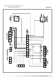
Fig. 3.31
FIG.
3.28
FIG. 3.27