
Technical information


44
SUPPLY PRESSURE (WORKING)
G20 methane 20 mbar
G31 pr
opane
37 mbar
1 3
2
4
2
4
3
1
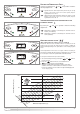
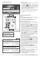
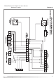
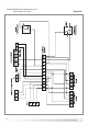
3.6.3 GAS REGULATION CHECK
Supply pressure check
1. Loosen screw “1” (Fig. 3.33) and connect the pressure gauge
connection pipe into the test point.
2
. Turn the boiler on at maximum power, enabling the “flue sweep”
function (press the key for 5 seconds and then press the
p
rogramming keys and together ensuring the dashes are
at the top of the display (see Fig. 3.30). The supply pressure
should correspond to that shown for the type of gas the boiler is
designed for methane gas G20 (see table below).
3. Disable the test mode by pressing the reset key.
4. When the check is over, tighten screw “
1” and test for tightness.
N
OTE:IF THE WORKING PRESSURE IS INSUFFICIENT CHECK THE GAS
METER, METER GOVERNOR, OR INSTALLATION PIPEWORK FOR
E
RROR
.
IMPORTANT!
D
O NOT PROCEED CHECKING AND ADJUSTING THE C
O
2 SETTINGS
UNLESS THE WORKING PRESSURE IS ADEQUATE
.
N
O
TE
:AL
L SETTINGS ARE TO BE MADE WITH A
CO2 M
ETER WITH THE
P
ROBE FITTED TO THE FLUE GAS ANALYSIS POINT
.
Setting the CO2 at minimum power
T
o check the air/gas ratio at minimum power, proceed as follows:
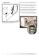
1. Connect the combustion analyser to the analysis point (Fig.
3.32) after removing the cover plate.
2. Set the boiler to minimum power via the test function (see
paragraph 3.6.1) or by pressing the button for 5 seconds
and then pressing the button on the control panel, ensure
the dashes are at the bottom of the display (see Fig. 3.30).
Ensure the CO
2 value on the analyser corresponds with the
value indicated in table 4D. If this is not the case, adjust screw
“2” (Fig.3.33) with a screwdriver in small intervals, allowing the
reading to become stable before adjusting further, until you
obtain the correct CO
2 reading. Allow the reading to become
stable for at least 4 minutes.
3. When the check is over, replace the cap on screw “
2” (Fig. 3.33).
4. Disable operation at minimum power by pressing the key
or press the key to check the maximum value (dashes at top
of displa
y see Fig. 3.31).
While the appliance is operating at maximum power, check
the gas rate of the appliance at the gas meter
Setting the CO2 at maximum power
To check the air/gas ratio at maximum power, proceed as follows:
1.
With the comb
ustion analyser already connected to the analysis
point, set the boiler to maximum power via the test function (see
paragraph 3.6.1) or by pressing the button for 5 seconds
and then the programming keys and ensuring the dashes
at the top of the display (see Fig. 3.30).
Ensure the CO
2 value on the analyser corresponds with the
v
alue indicated in
tab
le 4D
. If this is not the case, adjust screw
“
4” with a screwdriver in small intervals allowing the analyser
reading to stabilise before adjusting further (Fig. 3.33), until you
obtain the correct CO
2 reading. Allow the reading to become
stable for at least 4 minutes.
2. Disable the test mode by pressing the button.
The test mode is automatically disab
led after 5 min
utes
.
3.
Repeat the air/gas ratio at minimum power check (see
above).
4. Disconnect the analyser, remount the cover plate and check it is
securely in place
.
While the appliance is operating at minim
um po
wer
,
check
the gas rate of the appliance at the gas meter
N
OTE:WHEN MAKING ADJUSTMENTS, ADJUST SMALL AMOUNTS AND
W
AIT
FOR
THE
ANALYSER TO STABILISE BEFORE MAKING
FURTHER ADJUSTMENTS.
CO2 SETTING MAXIMUM VALUE
CO
2 at maxim
um power
% v
ol
8.7
±0.2 (NG)
%
v
ol
10.2 ±0.2 (LPG)
CO2 SETTING MINIMUM VALUE (NAT GAS)
CO2 at minimum power % vol 9.2 ±0.2 (NG)
% vol 10.6 ±0.2 (LPG)
SE
TTING THE
GA
S
PR
ESSURES
FIG. 3.32
FIG. 3.33
TABLE 4D
Analysis cover plate