
Technical information

53
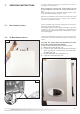
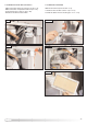
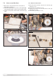
FIG. 7.1
7. SERVICING INSTRUCTIONS
The life of individual components vary and they will need servicing or
replacing as and when faults develop.
T
he fault finding sequence chart in chapter 2 will help to locate which
component is the cause of any malfunction, and instructions for
removal, inspection and replacement of the individual parts are given
in the following pages.
7.1. REPLACEMENT OF PARTS
7.2. TO GAIN GENERAL ACCESS
All testing and maintenance operations on the boiler require the
control panel to be lowered. This will also require the removal of the
casing.
To lower the control panel and dismantle the front
part of the casing, proceed as follows:
To remove the front casing panel, follow these steps:
1. Remove the screws “A” (Fig. 7.1);
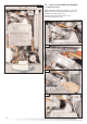
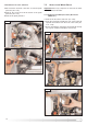
2. Loosen the four screws ‘B’ from the case hooks (two
at the top and two at the bottom) and rotate anti-
clockwise (Fig. 7.2);
3. Lift and unhook the case panel (Fig. 7.3);
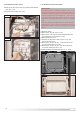
4. Lower the control panel (Fig. 7.4)
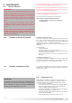
To ensure efficient safe operation, the boiler must be serviced
annually by a competent person.
Before starting any servicing work, ensure both the gas and
electrical supplies to the boiler are isolated and the boiler is
cool.
Before and after servicing, a combustion analysis should be made
via the flue sampling point (please refer to 3.6.3).
After servicing, preliminary electrical system checks must be carried
out to ensure electrical safety (i.e. polarity, earth continuity,
resistance to earth and short circuit).
A
A
FIG. 7.3
FIG. 7.2
B