
Technical information

54
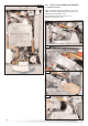
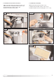
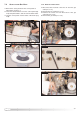
1. Disconnect the electrical connector “C” (FIG. 7.5);
2
.
D
isconnect the compensation tube “D” (F
IG.
7.5);
3. Remove the clip “E” (FI
G
. 7.6).
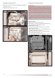
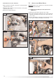
4
.
U
nscrew the four screws “F” (F
IG.
7.7);
5. Remove the fan (FIG. 7.8).
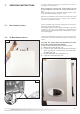
7.3. ACCESS TO THE COMBUSTION CHAMBER
7.3.1. RE
MOVING THE
FA
N
FIG. 7.6
E
FIG. 7.5
C
D
FIG. 7.7
FIG.
7.8
F
F
F
F
FI
G
. 7.4