
Technical information

55
FI
G
. 7.9
FI
G
. 7.10
H
G
I
I
1
.
D
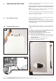
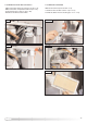
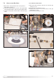
isconnect the electrical connector “G” (F
I
G
.
7.9);
2. Disconnect the compensation tube “H” (FIG. 7.9);
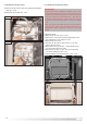
3. Unscrew the two screws “I” (FIG. 7.10);
4. Remove the Air Pressure Switch
7.3.2. RE
MOVING THE
AI
R
PR
ESSURE
SW
ITCH
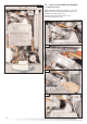
7.3.3. RE
MOVING THE
BU
RNER
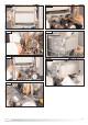
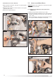
With the fan removed (see Section 7.3.1);
1
.
R
emove the four allen screws “J” (F
IG.
7.11);
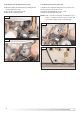
2. Slide the burner from its housing (FIG. 7.12 - 7.13).
FI
G
. 7.11
FIG. 7.12
FIG.
7.13
J