
Technical information

56
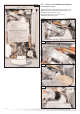
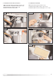
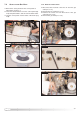
7.3.5. RE
MOVING THE
HE
AT
EX
CHANGER
1. Drain the boiler;
2. Remove the six nuts “L” (FIG. 7.16);
3. Remo
ve the C.H. flow and return temperature probe
unscrewing the screws “M” (FIG. 7.16);
4. Remove the front cover;
5. Unscrew the two allen screws “N” (FIG. 7.17) and
remove the clip (7.18);
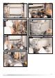
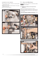
6. Remove the “U” clip “O” (FIG. 7.19) and remove the
C.H. flow water pipe (F
IG. 7.20);
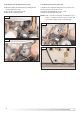
7. Remove the “U” clip “P” (FIG. 7.21) and remove the
C.H. return water pipe (FIG. 7.22);
8. Pull forward the heat exchanger (FIG. 7.23 - 7.24).
FIG. 7.16
FIG.
7.17
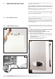
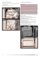
FIG. 7.14
FIG.
7.15
7.3.4. RE
MOVING THE
EL
ECTRODES
1. Remove the two allen screws “K”, pulling off the ignition
c
able (F
IG.
7.14);
3. Extract the electrodes (FIG. 7.15).
K
L
M
N
N
M
L
L
L
L
L
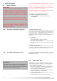
IMPORTANT!!
E
very time that the combustion chamber cover or the
primary heat exchanger is removed from the boiler, the
combustion chamber seal must be checked and where
necessary replaced (code: 65102217). The silicone
grease provided with the gasket must be spread
around the area the gasket fits to ensure an airtight
seal.
Only the grease provided must be used, however,
should more grease be needed it must have a
temperature range of between –40 deg C and +200
deg C”