
Technical information


9
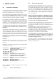
After removing the boiler from its packaging, remove the
template from the separate box containing the connection kit.
NO
TE
: Pay particular attention to any test water that may spill
from the appliance.
Place the template in the position the appliance is to be
mounted and after ensuring it is hanging squarely, use it to mark
the holes for the hanging bracket, connection kit and flue pipe(s)
NB: For further information relating to the flue installation please
refer to Section 2.9 F
L
UE
CO
NNECTION
. (If the appliance is to be
f
itted on a wall of combustible material, the wall
mu
st
b
e
protected by a sheet of fireproof material).
I
f the appliance is to be fitted into a timber framed building,
guidance should be sought from the Institute of Gas Engineers
d
ocument R
EF:
IGE/UP/7.
2.5.1. Drill the wall and plug using those supplied with the
connections kit, position the hanging bracket and secure with the
wall screws supplied, assemble the connection kit and secure to
the wall.
NO
TE
: It is highly recommended that a spirit level be
used to position the appliance to ensure that it is perfectly level.
2.5.2. Position the appliance on the hanging bracket and
connect the connection kit to the boiler connections. (see also
Sections 2.7 Gas Connections, 2.8 Water Connections & F
I
G
.
2.5).
For safety purposes, have a competent person carefully check
the electrical system in the property, as the manufacturer will not
be held liable for damage caused by the failure to earth the
appliance properly or by anomalies in the supply of power. Make
sure that the residential electrical system is adequate for the
maximum power absorbed by the unit, which is indicated on the
rating plate. In addition, check that the section of cabling is
appropriate for the power absorbed by the boiler.
85 mm
220 mm
2.5. MOUNTING THE APPLIANCE
2.6. ELECTRICAL CONNECTION
The boiler oper
ates with alter
nating current, as indicated in the
technical data table (Section
1.2), where the maximum absorbed
po
wer is also indicated. Make sure that the connections for the
neutral and live wires correspond to the indications in the
diagram. The appliance electrical connections are situated inside
the electr
ical bo
x (see
Section 2.12
).
IMPOR
T
ANT
!
In the event that the power supply cable must be changed,
replace it with one with the same specifications. Make the
connections to the ter
minal board located within the control
panel, as f
ollows:
- The yellow-green wire should be connected to the terminal
marked with the earth symbol; make sure to re-use the ferrule
mounted on the other supply cable;
-
The blue wire should be connected to the ter
minal marked
“N”;
- The brown wire should be connected to the terminal marked
“L”.
FIG. 2.4
2.7. GAS CONNECTION
The local gas region contractor connects the gas meter to the
service pipe.
If the gas supply for the boiler serves other appliances ensure
that an adequate supply is available both to the boiler and the
other appliances when they are in use at the same time.
Pipe work must be of an adequate size. Pipes of a smaller size
than the boiler inlet connection must not be used.
Note: The diagrams for the electrical system are indicated in
Sections 2.12 and 2.13.
Warning, this appliance must be earthed.
External wiring to the appliance must be carried out by a
competent person and be in accordance with the current I.E.E.
Regulations and applicable local regulations.
T
he appliance is supplied with a fly-lead already connected, this
must be connected to a 240v supply fused at 3A and must
f
acilitate complete electrical isolation of the appliance, by the
use of a fused double pole isolator having a contact separation
o
f at least 3 mm in all poles or alternatively, by
m
eans of a 3 A
fused three pin plug and unswitched shuttered socket outlet
b
oth complying with BS 1363.
The point of connection to the Electricity supply must be readily
accessible and adjacent to the appliance unless the appliance is
installed in a bathroom when this must be sited outside the
bathroom (see Section 2.2).
S
hould external controls be required, the design of the external
electrical circuits should be undertaken by a competent person,
see Sections 2.12 and 4 for further information.