Unvented Unvented water water heater heater
62 “Enactment of Directive 2012/19/EU governing electrical and electronic waste (WEEE)” The barred bin symbol on the appliance and its packaging indicates that the product must be scrapped separately from other waste at “Enactment of The Directive 2012/19/EU governing electrical and electronic waste the end of its service life.
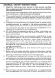
GENERAL SAFETY INSTRUCTIONS 1. Read the instructions and warning in this manual carefully, they contain important information regarding safe installation, use and maintenance. This manual is an integral part of the product. Hand it on to the next user/owner in case of change of property. 2. The manufacturer shall not liable for any injury to people, animals or damage to property caused by improper, incorrect or unreasonable use or failure to follow the instructions reported in this publication. 3.
jammed and to remove any scale deposits. 11. It is normal that water could drip from the Safety Relief Valve and EN 1487 safety unit while the appliance is heating up. The pressure relief valve should be fitted in accordance with the relevant G3 Building Regulations. 12. Make sure you drain the appliance and disconnect it from the power grid when it is out of service in an area subject to subzero temperatures. 13.
LEGIONELLA BACTERIA FUNCTION Legionella are small rod shaped bacteria which are a natural constituent of all fresh waters. Legionaries’ disease is a pneumonia infection caused by inhaling of Legionella species. Long periods of water stagnation should be avoided; it means the water heater should be used or flushed at least weekly.
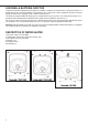
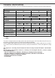
TECHNICAL SPECIFICATIONS For the technical specifications, refer to the nameplate (the nameplate is located next to the water intake/outlet pipes).
USER INSTRUCTIONS PLEASE KEEP THIS BOOKLET FOR FUTURE REFERENCE The heater is insulated to a high standard therefore it may be left on all the time. The temperature of the water may be adjusted by turning the knob on the front of the heater, allow half an hour for the temperature to stabilise between settings. Maximum temperature is achieved with the knob turned fully clockwise. The <> mark on the regulation knob indicates an <> setting and corresponds to a water temperature of 55 - 60°C.
INSTALLATION INSTRUCTIONS Before installing the heater read these instructions in full. If you are unsure please contact our technical service department (03332407777). Note: For further information please refer to the flow chart on page 19 which gives guidance on choosing controls. The installation must comply with all relevant Water Regulations/Byelaws and Building Regulations. The installer should check with the local water authority for confirmation of the maximum water supply pressure.
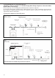
1) Using the feed pipe to accommodate expansion (Schedule 2, Section 6: Paragraph 15 of the Water Supply (Water Fittings) Regulations 1999 and the Water Byelaws 2000, Scotland) (Fig. 1). Do not fit any stop cocks or isolating valves within the distance required for expansion. If a pressure reducing valve is needed, due to a mains pressure of over 3.5 bar, an expansion control kit must be fitted regardless of expansion pipework installed.
The model 30L is covered under the Building Regulations and therefore it is not possible to accommodate the expansion water within the system pipe work and consequently a set of expansion controls must be installed. Note: The discharge from relief valves must be made in a safe and conspicuous manner; therefore a tundish (Kit C) is available for 10 and 15 litre units if required.
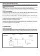
iii) Discharges at high level; i.e. into a metal hopper and metal down pipe with the end of the discharge pipe clearly visible (tundish visible or not). Or onto a roof capable Fig. 4 Suggest ways of terminating discharge pipes safety Temperature & pressure relief valve Metal discharge pipe (D1) from temperature & pressure relief valve to tundish. Tundish 600 mm Max. 300 mm Min. Discharge below fixed grating. (see page 6 for alternative points of discharge).
Worked example The example below is for a G 1/2” temperature & pressure relief valve with a discharge pipe (D2) having 4 no. elbows and length of 7 m from the tundish to the point of discharge. From Table 2 Maximum resistance allowed for a straight length of 22 mm copper discharge pipe (D2) from G 1/2” T & P valve is 9 m. ELECTRICAL Subtract thed) resistance for 4 no. 22WARNING: mm elbows at 0.8 m each = 3.2 m. Therefore the maximum permitted length to: 5.8 m. The appliance must beequates earthed As 5.
- Check that the discharge pipe drains safely to waste and is readily visible. Check, in the case where some components are not factory fitted, that they are marked so as to refer to the warning label on the water heater. Open all outlet taps. Turn on the mains water supply. Close taps in turn as water flow stabilises with no air bubbles. Check for leaks. Check that no water is passing through the safety valve(s).
2) Pressure relief valve dripping/running all the time. Cause: Mains pressure is above 3.5 bar. A pressure reducing valve must be fitted (see fig. 2). 3) Dripping while unit heating. Cause: Not enough pipe work for expansion; or stop-cock, non-return valve or pressure reducing valve has been fitted on the cold mains supply (see fig. 2). If an expansion vessel has been fitted, the charge may have failed. 6) No water at all. 4) No hot water. Cause:cut-out Valve has incorrectly Cause: Thermal operated.
WE MAKE USE OF RECYCLED PAPER Manufactured by: Commercial subsidiary: Ariston Thermo S.p.A. Ariston Thermo UK Ltd Viale Aristide Merloni, 45 60044 Fabriano (AN) Tel. (+ 39) 0732 .6011 ariston.com Artisan Building Hillbottom Road High Wycombe HP12 4HJ www.ariston.co.uk e-mail: info.uk@aristonthermo.