Three Element Commercial Electric Water Heaters Use and Care Manual Installation Start-Up Maintenance Parts Warranty This manual must only be used by a qualified installer / service technician. Read all instructions in this manual before installing. Perform steps in the given order. Failure to do so could result in substantial property damage, severe personal injury, or death.
The following defined terms are used throughout this manual to bring attention to the presence of hazards of various risk levels or to important product information. IMPORTANT SAFETY INSTRUCTIONS When using electrical appliances, basic safety precautions to reduce the risk of fire, electric shock, or injury to persons should be followed, including: DANGER indicates an imminently hazardous situation which, if not avoided, will result in serious personal injury or death. 1.
Table of Contents Part 1 - General Safety Information A. When Servicing the Water Heating System B. Heater Water C. Freeze Protection D. Water Temperature Adjustment Part 2 - Prepare the Water Heater A. What’s in the Box B. Locating the Water Heater C. Water Chemistry Requirements Part 3 - Piping A. Plumbing B. Thermal Expansion C. Condensation D. Insulation Blankets E. Temperature and Pressure Relief Valve F. Scalding G. Filling the Heater H.
D. Water Temperature Adjustment thermostat is factory set at 125°F (51,7°C) or lower to reduce the risk of scalding injury If the water heater is going to have a set temperature above 120oF, it is recommended to use an ASSE 1017 rated mixing valve to avoid severe burns or death from scalding temperatures. Households with small children, disabled, or elderly persons may require a 120oF or lower temperature setting to prevent severe personal injury or death due to scalding.
If you suspect that your water is contaminated in any way, discontinue use of the appliance and contact an authorized technician or licensed professional. • Water pH between 6.5 and 8.5 • pH levels below 6.5 can cause an increase in the rate of corrosion. pH of 8.5 or higher can potentially cause lime scale build-up • Maintain water pH between 6.5 and 8.5. Check with litmus paper or have it chemically analyzed by a local water treatment company. • If the pH is not between 6.5 and 8.
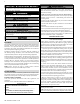
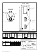
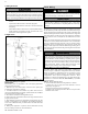
FRONT VIEW D TEMP/PRESSURE RELIEF VALVE TOP VIEW E HOT WATER OUTLET COLD WATER INLET F C B ELEMENT AND THERMOSTAT ACCESS LP-647-D 06/17/2021 A Figure 2 - Dimensional Drawing Specifications and Dimensions Models Storage Capacity A B C D 080 80 6 1/2” 60” 69” 23 1/4” 100 100 52” 61” 115 115 60” 69” 7 1/4” 27” E Water Temperature Ratings F 26” 8” 30” Table 2 - Specifications and Dimensions - See Table 3 for a List of Available Elements Gallons 80, 100, 115 # Elements and
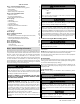
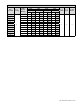
Electrical Specifications Full Load Current In Amperes Total Input (Kw) # of Elements Single Element Wattage 208V 240V 277V 480V Phase Phase Phase Phase 1 3 1 3 1 3 1 3 4.1* 4.1 20 20 - - - - - - 4.5* 4.5 22 22 19 19 17 17 10 10 5* 5 - - 21 21 18 18 11 11 5.5* 5.5 - - 23 23 19 19 12 12 6* 6 - - - - 22 22 13 13 12.5 4.2 60 35 - - - - - - 4.5 65 38 57 33 - - 29 17 14 4.
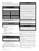
Part 3 - Piping A. Plumbing It is mandatory that all plumbing be done in accordance with federal, local, and state plumbing codes and practices. Failure to properly install the water heater WILL VOID the warranty. It is also necessary to use both thread tape and pipe dope on all mechanical plumbing connections. Install unions on the hot and cold water connections to easily disconnect the water heater for servicing.
F. Scalding Do not thread a cap or plug into the relief valve or relief valve line under any circumstances! Explosion and property damage, serious injury, or death may result. To avoid water damage or scalding due to relief valve operation: • Discharge line must be connected to relief valve outlet and run to a safe place of disposal. Terminate the discharge line in a manner that will prevent possibility of severe burns or property damage should the relief valve discharge.
G. Filling the Heater When filling the water heater, open a hot water tap to release air in the tank and piping. The tank must be full of water before the heater is turned on. Failure to ensure the water heater is full before turning it on could result in damage to the water heater and other property damages. Such damages ARE NOT covered by water heater warranty. • Make certain that the field installed drain valve is completely closed. • Open the shut-off valve in the cold water supply line.
Figure 4 - Converting from Single to 3 Phase Operation b. To convert from Simultaneous to Non-Simultaneous element operation: 1. Remove the purple wire from the bottom side of the fuse holder and place it in the terminal block slot with the adjoining purple wire. 2. Remove the orange wire from the bottom side of the fuse holder and place it in the terminal block slot with the adjoining orange wire. 3.
SIMULTANEOUS SIMULTANEOUS Figure 7 - Factory Wiring - Single Phase, Simultaneous Operation Figure 8 - 3 Phase, Simultaneous Operation Figure 9 - Factory Wiring - Single Phase, Non-Simultaneous Operation Figure 10 - 3 Phase, Non-Simultaneous Operation ahl-647 Revision Date 7.12.
Part 5 - Installation Checklist Water Heater Location Yes No SHOULD NOT be removed. Set temperature indicator to desired temperature. Replace insulation and the black access cover. Turn on power to the heater. Close to area of heated water demand Indoors and temperatures protected from Failure to disconnect the power from the water heater before attempting to adjust or reset the thermostat(s) will result in property damage, severe personal injury, or death.
bled. C. Heating Element Replacement Procedure If heating elements need replacement, it is very important to use the same voltage, wattage, and construction. DO NOT replace heating element with a generic heating element. Only Ariston heating elements are approved for use with this water heater. Failure to follow this warning will result in premature product failure and VOID the warranty, and could result in severe personal injury or death.
water deposits. Once complete, close the drain valve and restore power to the water heater. Water drained from the water heater may be scalding hot. Take care to avoid scalding. Wear gloves and safety glasses, and direct water to a safe drainage location. It is recommended to turn power off to the water heater and run water at a hot water faucet until it cools BEFORE draining water from the heater. Failure to comply with this warning could result in property damage, severe personal injury, or death.
Part 8 - Troubleshooting Problem Reason Remedy Manual disconnect switch turned off No Hot Water Not Enough Hot Water Water Too Hot or Not Hot Enough 1. 2. 3. 4. Turn switch on Blown fuse or circuit breaker tripped Shorted or improper wiring Circuit overloaded Grounded element or thermostat 1. 2. 3. 4. Replace fuse or reset breaker *Replace, repair, or rewire per detail *Provide adequate circuit to reduce load *Replace Manual Reset High Limit (ECO) open 1.
Part 9 - Replacement Parts 8 7 LP-647-E 06/17/2021 13 11 13 16 9 17 13 9 1 12 18 17 10 3 15 14 19 1 19 18 4 ITEM# 1 2 3 4 5 6 7 8 10 9 3 5 2 18 10 11 12 19 13 4 14 15 16 17 18 19 10 6 DESCRIPTION THERMOSTAT - UPPER, MIDDLE THERMOSTAT LOWER THERMOSTAT PROTECTIVE COVER ACCESS PANEL SCREWS - ACCESS PANEL DRAIN VALVE NIPPLE - HEAT TRAP DIP TUBE - 100 GAL. DIP TUBE - 80/115 GAL.
Medium Duty Commercial Stainless Steel Electric Water Heater Limited Warranty OWNER RESPONSIBILITIES Ariston warrants each medium duty commercial stainless steel electric water heater and its components to be free from defects in materials and workmanship according to the following terms, conditions, and time periods. UNLESS OTHERWISE NOTED THESE WARRANTIES COMMENCE ON THE DATE OF INSTALLATION.
component / attachment not supplied by Ariston. 18. Damages, malfunctions, or failures caused by abuse, accident, fire, flood, freeze, lightning, electrochemical reaction, acts of God and the like. 19. Tank failures (leaks) caused by operating the water heater in a corrosive or contaminated atmosphere. 20.
Customer Installation Record Form The following form should be completed by the qualified installer / service technician for you to keep as a record of the installation in case of a warranty claim. After reading the important notes at the bottom of the page, please also sign this document.