
Use and Care Manual


ahl-647 Revision Date 7.12.23
10
G. Filling the Heater
• Make certain that the eld installed drain valve is completely
closed.
• Open the shut-o valve in the cold water supply line.
• Open the hot water faucets to allow air to vent from the heater
and piping.
• Allow sucient time for the heater to completely ll with water.
• Verify elements are installed correctly. Check for leaks at the
water heater and throughout the system.
When lling the water heater, open a hot water tap to release air in
the tank and piping. The tank must be full of water before the heater
is turned on. Failure to ensure the water heater is full before turning
it on could result in damage to the water heater and other property
damages. Such damages ARE NOT covered by water heater warranty.
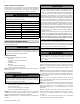
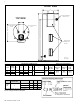
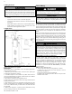
Figure 3 - Piping Detail - NOTE: Drawing is meant to demonstrate system
piping concept. Heat traps are optional.
H. Applications
PIPING NOTES:
The following notes are applicable to all of the piping applications
demonstrated on this page.
1. Minimum pipe size should match connection size. Upsize pipe
accordingly if greater ow is required.
2. A thermal expansion tank suitable for potable water must be
sized and installed within this piping system between the backow
preventer and the cold water inlet.
3. All circulators should have an integral ow check.
4. Drains and check valve between unit and storage tank will assist in
purging air from system.
5. These drawings are meant to demonstrate system piping only. The
installer is responsible for all equipment and detailing required by
local codes. In Massachusetts, you must install a vacuum relief valve
per 248 CMR.
6. Mixing valve application is optional, but recommended to help
prevent scalding. See Part 3 for more information.
Part 4 - Wiring
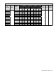
This unit is equipped with a terminal block for easy connection to
el wiring and conversion. These heaters are equipped and wired
for the maximum possible input allowable (see Table 4 for listing of
inputs and amperage requirements). The voltage requirement and
dedicated wattage load for the heater is specied on the rating label
of the water heater. Consult your local power company to determine
if your electrical service is adequate for the additional load of the
heater.
Refer to the wiring diagrams for eld connections. All wiring must
conform to local code and the National Electric Code, and should be
done by a qualied licensed electrician or the local electric utility.
Grounding can be accomplished by using approved conduit and
ttings or other approved conductive material. A grounding wire is
provided on the junction bracket. This grounding wire must be used
in the installation.
Tank must be full of water before the power is turned on. Heating
elements will be damaged if energized for even a short time
while tank is dry. Failures due to “dry-ring” ARE NOT covered by
warranty.
Be sure to ground the water heater. The preferred way to ground
is with rigid metal conduit between the main panel and the water
heater junction box with approved end ttings (check codes on
the use of exible conduit). If making a separate ground, a green
ground wire is provided in the water heater junction box. Replace
the junction box cover and insulation after you have made the
wiring connections. Failure to follow these instructions could
result in property damage, severe personal injury, or death.
Alternate Wiring / Operation Congurations
The water heater ships ready for Single Phase, Simultaneous
operation. Figure 7 details this conguration. This factory installed
wiring and operation conguration may be converted to meet
custom installation conditions. Figures 8 - 10 detail these optional
congurations. These optional congurations include: 3 Phase
Simultaneous, 3 Phase Non-Simultaneous, and Single Phase Non-
Simultaneous. Conversions MUST BE PERFORMED by a Qualied
Service Technician.
STEP #1 – Wiring the Water Heater
a. To convert the water heater from Single Phase to 3 Phase:
1. Remove the red and grey wires from terminals L1 and L2
respectively. See Figure 4.
2. Place the red and grey wires in terminal L3.
3. Tighten screws to securely hold wires. Be sure not to place wire
insulation under screws.
Failure to disconnect the power from the water heater before
attempting wiring or conversion will result in property damage,
severe personal injury, or death due to electric shock.