
Installation Guide

LP-722 Rev. 000 Rel. 000 Date 9.3.19
WARNING
!
This Quick Start Guide DOES NOT replace the Use and Care Manual. Read and
comprehend the Use and Care Manual before installing this product.
Step 1 - Before Installing
Quick Start Guide
Models: 3kW / 6.5kW / 10.5kW / 13kW
This product must only be installed by a qualied installer / service technician.
The manufacturer will not be held liable for any damages resulting from im-
proper installation.
Follow all local codes as well as the most recent edition of the latest version of
the National Electrical Code, NFPA No. 70.
When applicable, the installation must conform with Manufactured Home
Construction and Safety Standards, Title 24 CFR, Part 3280 and/or CAN/CSA
Z240 MH Series Mobile Homes.
Failure to follow these instructions before installation could result in property
damage, personal injury or death.
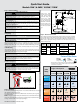
Step 2 - Installing
Inlet
Temp.
Single & Multipoint
110-120V
3.1-3.5 KW
240V
6.5 KW
240V
10.5 KW
240V
13 KW
40
º
F
Max Flow Rate
.7 GPM 1.1 GPM 1.4 GPM
50
º
F
Max Flow Rate
.5 GPM
.8 GPM 1.3 GPM 1.6 GPM
60
º
F
Max Flow Rate .5 GPM 1 GPM 1.6 GPM 2 GPM
70
º
F
Max Flow Rate .6 GPM 1.3 GPM 2 GPM 2.5 GPM
Fixture Flow Rates
Shower
1.5 GPM
(Range 1.5 -2.5)
Sink
.5 GPM
(Range .5 -1.5)
- Max Flow Rate Calculated for 105
º
F Outlet Water Temperature
- Standard Install is 240V, if 208V is used Increase One Model
Size from the Chart Below
NOTICE
Any claims for damage or shortage in shipment must be led immediately
against the transportation company by the consignee.
A. Unpacking
B. Location Requirements
Choose a location for the water heater as centralized to the piping and electrical
system as possible, and where domestic water piping will not be exposed to
freezing temperatures. All piping should be insulated. Additionally, place the
water heater so that the drain, controls, and inlets/outlets are easily accessible.
C. Wall Mounting
The mounting surface must be solid and secure. Do not install the unit above
electrical boxes or junctions. Ensure the unit is level. Mount the unit to the wall
with four (4) screws of at least one (1) inch in length.
NOTICE
Use screws suitable for the wall material and the weight of the water heater.
Failure to do so could result in property damages and damage to the water
heater. Such damages ARE NOT covered by product warranty.
The appliance must be mounted horizontally, with water inlets and outlets at
the bottom. See Figure 1.
WARNING
!
This water heater must be installed upright in the vertical position as described
in this manual. DO NOT attempt to install this water heater in any other orien-
tation. Doing so will result in improper water heater operation and property
damage, and could result in serious personal injury or death.
Figure 1 - DO NOT INSTALL THE WATER HEATER UPSIDE DOWN
AURES
SLIM MULTI
AURES
SLIM MULTI
√
Step 3 - Plumbing
It is mandatory that all plumbing be done in accordance with federal, local, and
state plumbing codes and practices.
The supplied pressure relief device (PRD) must be installed to protect against
excessive pressures.
NOTE: It is highly recommended by the manufacturer to install water leak detec-
tion devices and automatic shuto valves in any water heater installation where
a leakage of water could result in property damages.
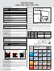
Figure 2 - General Piping Detail
Step 4 - Electrical Connection
The voltage requirement and dedicated wattage load for the heater is specied
on the water heater rating label. Consult your local power company to deter-
mine if your electrical service is adequate for the additional load of the heater.
Make secure, appropriate wiring connections to the water heater per the
National Electric Code.
Table 1 - Technical Specications - *Wattage based on maximum voltage.
Connect the water
inlet line to the entry
point of the heater
(left side inlet), and
connect the outlet
line to the water out-
let. Use a line that can
withstand a minimum
pressure of 58 psi. Us-
ing any other type of
line will cause dam-
age.
*Wattage
(kW)
Voltage Amperage Phase Circuit Breaker Size
Required Wire
Size
3 120 25
1
1 x 30
10 AWG
6.5
240
27 1 x 30
8.5 36 1 x 40
6 AWG
10.5 44 1 x 50
13 54 1 x 60 4 AWG
AUTOMATIC WATER
SHUT-OFF VALVE
(OPTIONAL)
HOT WATER OUTLET
BALL VALVE
CHECK VALVE
UNION
MIXING VALVE
(OPTIONAL)
PRESSURE
RELIEF
COLD WATER INLET
LP-683-A
10/23/18
CATCH
PAN
DRAIN
WATER LEAK
DETECTION
SENSOR (OPTIONAL)