A/23 MFFI - A/27 MFFI G.C.N.
TABLE OF CONTENTS 1. GENERAL INFORMATION 1.1 General Instructions 1.2 Technical Information 1.3 Overall View 2. INSTALLATION 2.1 2.2 2.3 2.4 2.5 2.6 2.7 2.8 2.9 2.10 2.11 2.12 Reference Standards Siting the Appliance Overall Dimensions Clearances Mounting the Appliance Electrical Connection Gas Connection Water Connections Flue Connection Room Thermostat Connection Electrical/System Diagrams Water Circuit Diagrams 3. COMMISSIONING 3.1 3.2 3.3 3.4 3.5 3.6 3.7 3.8 3.
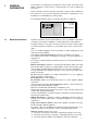
1. GENERAL INFORMATION This manual is an integral and essential part of the product. It should be kept with the appliance so that it can be consulted by the user and our authorised personnel. Please carefully read the instructions and notices about the unit contained in this manual, as they provide impor tant information regarding the safe installation, use and maintenance of the product. For operating instructions please consult the separate User’s Manual. User’s Manual A/23 MFFI A/27 MFFI 1.
chamber visually. 4 - Visual check of the combustion: clean burners if necessary. 5 - With reference to point 3, dismantle and clean the combustion chamber if necessary. 6 - With reference to point 4, dismantle and clean the injectors if necessary. 7 - Visual check of the primary heat exchanger: - check for overheating of the exchangers fins; - clean the exhaust side of the exchanger and fan if necessary. 8 - Regulate the gas pressure, ignition pressure, partial flame, maximum flame.
1.3 Overall View A/23 MFFI - A/27 MFFI Fig. 1.1 Legend: 1. 2. 3. 4. 5. 6. 7. 8. 9. 10. 11. 12. 13. B023 Flue Connector Combustion Chamber Hood Main Heat Exchanger Combustion Chamber Insulation Panel Burner Expansion Vessel Overheat Thermostat Spark Generator Diverter Valve Main Circuit Temperature Probe Main Circuit Flow Switch Diverter Valve Microswitch Filter Seat 14. 15. 16. 17. 18. 19. 20. 21. 22. 23.
2. INSTALLATION The technical information and instructions provided herein below are intended for the installer so that the unit may be installed correctly and safely. 2.1 Reference Standards The installation and initial start up of the boiler must be by a CORGI Approved Installer in compliance with the installation standards currently in effect, as well as with any and all local health and safety standards i.e. CORGI .
Overall Dimensions 890 2.3 (A-B-D-E) 36 5 (C) 465 Fig. 2.1 Legend: A = Central Heating Flow (3/4”) B = Domestic Hot Water Outlet (1/2”) C = Gas Inlet (3/4”) D = Domestic Cold Water Inlet (1/2”) E = Central Heating Return (3/4”) 2.4 Clearances In order to allow for access to the interior of the boiler for maintenance purposes, the boiler must be installed in compliance with the minimum clearances indicated in the diagram below.
2.5 Mounting the Appliance Fasten the boiler in place using the template and anchors supplied with the unit. It is highly recommended that a spirit level be used to position the boiler so that it is perfectly level. For additional information, please consult the instructions contained in the connection kit and the flue kit. 2.
2.9 Water Connections A/23 MFFI - A/27 MFFI C A B D E I Fig. 2.4 Legend A = Central Heating Flow B = Domestic Hot Water Outlet C = Gas Inlet D = Domestic Cold Water Inlet E = Central Heating Return I = Safety Valve Central Heating Detailed recommendations are given in BS 6798:1987 and BS 5449-1:1990, the following notes are given for general guidance. Pipe Work: Copper tubing to BS EN 1057:1996 is recommended for water pipes.
public access. Air Release Points: These must be fitted at all high points where air naturally collects and must be sited to facilitate complete filling of the system. The appliance has an integral sealed expansion vessel to accommodate the increase of water value when the system is heated. It can accept up to 7 l (1.5 gal) of expansion water. If the heating circuit has an unusually high water content, calculate the total expansion and add an additional sealed expansion vessel with adequate capacity.
BC F G F D HI J A E L Fig. 2.5 K G TERMINAL POSITION mm A - Directly below an open window or other opening B - Below gutters, solid pipes or drain pipes C - Below eaves D - Below balconies or car-port roof E - From vertical drain pipes and soil pipes F - From internal or external corners G - Above ground or below balcony level H - From a surface facing a terminal I - From a terminal facing a terminal J - From an opening in the car port ( e.g.
This procedure must be done as follows: 1 - Remove the air vent intake you want to use, in the area indicated in Fig. 2.8, by breaking the perforated ring. 2 - Use a tool to grasp the lid and remove it completely. 3 - Clean any burrs or sharp edges with a knife or an appropriate tool. A Fig. 2.8 Fig. 2.9 In Fig. 2.10 below, several different types of flue systems are shown. For additional information regarding the flue accessories, please consult the Flue Pipe Accessories manual. Fig. 2.
Exhaust Type Coaxial System Twin Pipe Systems Maximum Extension Diameter of Pipes Use of a Restrictor Exhaust/Air (mm) on the Discharge Side C12 (xx) 4m ø 60 /100 L* < 0.5 m C32 (xx) 4m ø 60 /100 L* < 0.5 m C42 (xx) 4m ø 60 /100 L* < 0.5 m Risk of Condensation Forming 23 kW 27 kW C12 (xy) 54 m 46 m ø 80 L < 7 m (23 kW) L < 5 m (27 kW) L > 4 9 m (23 kW) L > 6.5 m (27 kW) C32 (xy) 54 m 46 m ø 80 L < 7 m (23 kW) L < 5 m (27 kW) L > 4.9 m (23 kW) L > 6.
2.10 Room Thermostat Connection In order to perform this procedure, remove boiler cover as indicated in section 3.2. Then proceed as follows: 1 Remove the screws “A” located on the bottom part of the boiler; 2 Widen the sides so that the control panel can be rotated. 3 Open the cover “B” on the left hand side of the compartment. 4 Insert the wire for the connection of the room thermostat into the wire holder “C”, as indicated in photo 3.
2.11 Electrical Diagram Legend: AT BT B C D E F G H I J K M N O P Q R S T U V W X Aa Y = = = = = = = = = = = = = = = = = = = = = = = = = = High Voltage P.C.B. Low Voltage P.C.B. Flame Failure L.E.D. Insufficient Water Pressure L.E.D. Water Temperature Indicator L.E.D.s Overheat Thermostat Warning L.E.D. System Reset Button Selector Knob for Operating Mode Domestic Hot Water Temp. Adjustment Central Heating Temp.
A/23 MFFI - A/27 MFFI A/23 MFFI - A/27 MFFI EX C-MI/FFI 8 16 B023
2.12 Water Circuit Diagram A/23 MFFI - A/27 MFFI 3 COMMISSIONING 3.1 Initial Preparation Legend 1. Air Pressure Switch 2. Fan 3. Main Heat Exchanger 4. Main Burner 5. Ignition Electrodes Detection Electrode 6. Gas Valve 7. Overheat Thermostat 8. Main Circuit Temperature Probe 9. Diverter Valve 10. Main Circuit Flow Switch including Safety Pressure Switch for Primary Circuit 11. Automatic By-pass 12. Microswitch for Diverter Valve 13. Secondary Heat Exchanger 14. Domestic Water Inlet Filter 15.
system (sect. 3.4) and run it until the temperature has reached the boiler operating temperature. The system must then be immediately flushed through. The flushing procedure must be in line with BS 7593:1992 Code of practice for treatment of water in domestic hot water central heating systems. During this operation, we highly recommend the use of a central heating flushing detergent (Fernox Superfloc or equivalent), whose function is to dissolve any foreign matter that may be in the system.
3.4 Initial Start-up The checks to be run before initial start-up are as follows: 1.
G20 G25 G30-31 5.5 mm c.a. 4.5 mm c.a. 1.8 mm c.a. - the potentiometer for the maximum thermal power for the heating system, maximum thermal power setting (factory set at the maximum value, unless indicated otherwise on the adhesive sticker located in proximity to the potentiometer); - The connection for the diagnostic device (TCS-TCS2). 3.6 Combustion Analysis The boiler is designed to make it easy to analyse the combustion by-products.
off status. After the system has been allowed to cool, the system can be reset by pressing the button “A”. 4 - Limescale Build-up This is an indirect control (actuated through the regulation of the temperature in the primary heat exchanger) on the formation of limescale in the secondary heat exchanger. Regardless of the flow rate and the temperature in the circuit for the domestic hot water, the temperature is limited to 62°C. 5 - Safety Shut-off At the start of every lighting phase, the P.C.B.
4.1 Changing the Type of Gas CATEGORY II2H3+ Recommended Soft-Light Pressure (mbar) The boiler can be converted to use either methane (natural) gas (G20) or LPG (G30 - G31) by an Authorised Service Centre. The operations that must be performed are the following: 1. Replace the jets on the main burner (see table in section 4); 2. Adjust the maximum and minimum thermal capacity values for the boiler (see table in section 4); 3. Replace the gas rating plate; 4.
240V MAINS INPUT (3 AMP) 3 8 2 2 T6360B ROOM THERMOSTAT ZONE 2 L 1 N 2 E 3 8 E 1 2 E 4 E E E 5 N N 3 4 N 7 6 L L N L L 3 L 6 ZONE 2 4 Randall 3020 P and 3060 4 1 2 6 E E N HW HTG ON ON 1 0 1 0 E E N L N N N 2 2 1 L 2 N N L L L L L 1 1 2 L ZONE 1 PROGRAMMER 3 Randall 922, 972 Link L-2-5 ACL LS522, LS722 3 6 Towerchron MP Link 1-4/6-11 Towerchron 2000 6 Towerchron FP Link 1-5/4-7-9 3 4 1 4 • 3 ZONE 1 6 7 Sunvic ET 1451
1 2 B023 N C/P E 1 3 1 2 2 E T6360B ROOM 240VTHERMOSTAT MAINS INPUT (3 AMP) Cylinder thermostat L Thermal 1 1 8 N 2P 6 cut-out 1 C/P 240V MAINS INPUT (3 AMP) 3 2 V4043H VALVE HOT WATER VALVE 6 • 9 8 • 10 3 2 • 9 • 10 ZONE 2 Not used • 8 If a room thermostat is not requied on Zone 1, insert a link between 4 + 5 on the junction box. If a room thermostat is not requied on Zone 2, insert a link between 6 + 8 on the junction box.
NOTES 25 B023
NOTES B023 26
B023
STAMPA: Azienda Grafica BIEFFE srl - Recanati Merloni TermoSanitari SpA - Italy Commercial subsidiary: MTS (GB) LIMITED MTS Building Hughenden Avenue, High Wycombe Bucks HP13 5FT Telephone: (01494) 755600 Fax: (01494) 459775 Technical Service Hotline: (01494) 539579 Cod.