Installation Instructions Type C Boilers G.C.
TABLE OF CONTENTS 1. GENERAL INFORMATION 1.1 General Instructions 1.2 Technical Information 1.3 Overall View 2. INSTALLATION 2.1 2.2 2.3 2.4 2.5 2.6 2.7 2.8 2.9 2.10 2.11 2.12 Reference Standards Siting the Appliance Overall Dimensions Clearances Mounting the Appliance Electrical Connection Gas Connection Water Connections Flue Connection Room Thermostat Connection Electrical/System Diagrams Water Circuit Diagrams 3. COMMISSIONING 3.1 3.2 3.3 3.4 3.5 3.6 3.7 3.8 3.
1. GENERAL INFORMATION This manual is an integral and essential part of the product. It should be kept with the appliance so that it can be consulted by the user and our authorised personnel. Please carefully read the instructions and notices about the unit contained in this manual, as they provide impor tant information regarding the safe installation, use and maintenance of the product. For operating instructions please consult the separate User’s Manual. User’s Manual 1.
3 - Check the general condition of the appliance and of the combustion chamber visually. 4 - Visual check of the combustion: clean burners if necessary. 5 - With reference to point 3, dismantle and clean the combustion chamber if necessary. 6 - With reference to point 4, dismantle and clean the injectors if necessary. 7 - Visual check of the primary heat exchanger: - check for overheating of the exchangers fins; - clean the exhaust side of the exchanger and fan if necessary.
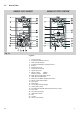
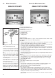
1.3 Overall View GENUS 23/27/30 MFFI GENUS 27 RFFI SYSTEM Fig. 1.1 Legend: 1. 2. 3. 4. 5. 6. 7. 8. 9. 10. 11. 12. 13. 14. 15. 16. 17. 18. 19. 20. 21. 22. 23. 24.
2. 2.1 INSTALLATION Reference Standards The technical information and instructions provided herein below are intended for the installer so that the unit may be installed correctly and safely. The installation and initial startup of the boiler must be by a CORGI Approved Installer in compliance with the installation standards currently in effect, as well as with any and all local health and safety standards i.e. CORGI.
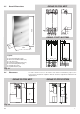
GENUS 23/27/30 MFFI Overall Dimensions 890 2.3 (A-B-D-E) (C) GENUS 27 RFFI SYSTEM 5 38 465 30 A = Central Heating Flow (3/4”) B = Domestic Hot Water Outlet (1/2”) C = Gas Inlet (3/4”) D = Domestic Cold Water Inlet (1/2”) E = Central Heating Return (3/4”) F = Cylinder Flow (3/4”) G = Cylinder Return (3/4”) 99 85 99 (F - G) 155 132 AF 67 65 49 Legend: (A - D - E) (C) 208 C DGE Fig. 2.1 2.
2.5 Mounting the Appliance Fasten the boiler in place using the template and anchors supplied with the unit. It is highly recommended that a spirit level be used to position the boiler so that it is perfectly level. For additional information, please consult the instructions contained in the connection kit and the flue kit. 2.
2.8 Water Connections View of the Boiler Connections GENUS 23/27/30 MFFI GENUS 27 RFFI SYSTEM C C A B D E A D I I F Legend E G Fig. 2.4 A = Central Heating Flow B = Domestic Hot Water Outlet C = Gas Inlet D = Domestic Cold Water Inlet E = Central Heating Return F = Cylinder Flow G = Cylinder Return I = Safety Valve Fig. 2.5 Fitting the connection kit to the Genus 27 RFFI System only. It will be noted that the kit has two connections not required for this boiler i.e.
Air Release Points: These must be fitted at all high points where air naturally collects and must be sited to facilitate complete filling of the system. The appliance has an integral sealed expansion vessel to accommodate the increase of water value when the system is heated. It can accept up to 7 l (1.5 gal) of expansion water. If the heating circuit has an unusually high water content, calculate the total expansion and add an additional sealed expansion vessel with adequate capacity.
A suitable terminal guard is available from: TOWER FLUE COMPONENTS Morley Road Tonbridge Kent TN9 1RA The minimum acceptable spacing from the terminal to obstructions and ventilation openings are specified in Fig. 2.
In addition, it is also possible to use a split system by fitting a special adapter to the flue discharge collar and using one of the apertures for the air vent intake located on the top part of the combustion chamber (A). Ø 80 mm A A A Ø 80 mm Fig. 2.8 This procedure must be done as follows: 1 - Remove the air vent intake you want to use, in the area indicated in Fig. 2.9, by breaking the perforated ring. 2 - Use a tool to grasp the lid and remove it completely.
In Fig. 2.11 below, several different types of flue systems are shown. For additional information regarding the flue accessories, please consult the Flue Pipe Accessories manual. Fig. 2.
Coaxial Systems Twin Pipe Systems Exhaust Type 30 kW Use of Restrictor on Discharge Side L * < 0.5 m 27 kW L * < 0.5 m 23kW L * < 0.5 m 45 mm 30 kW ø 60/100 42 mm 23kW 27 kW 3m Diameter of Pipes (mm) 4m L * < 0.5 m Maximum Extension Exhaust/Air 23 kW - 27 kW 30kW C12 (xx) L * < 0.5 m L > 4.5 m L * < 0.5 m L > 6.5 m L > 4.5 m ø 60/100 L > 4.9 m L > 6.5 m L > 4.5 m 3m L < 7.5 m L > 4.9 m L > 6.5 m L > 4.5 m 4m L<5m L < 7.5 m L > 4.9 m L < 5.3 m C32 (xx) L<7m L<5m L < 7.
2.10 Room Thermostat Connection In order to perform this procedure, remove the boiler casing as indicated in section 3.2. Then proceed as follows: 1 Remove the two screws “A” in order to remove the cover, release the two clips “B” and lift and rotate down the control panel box. 2 Open the cover “C” on the left hand side of the compartment. 3 Insert the wire for the connection of the room thermostat into the cable clamp “D”, as indicated in photo 3.
2.11 Electrical Diagram Legend: AT BT A B C D E F G H I J K L M N O P Q R S T U V W X Y Z Aa = = = = = = = = = = = = = = = = = = = = = = = = = = = = = High Voltage P.C.B. Low Voltage P.C.B. Remote Connector Kit Flame Failure L.E.D. Insufficient Water Pressure L.E.D. Water Temperature Indicator L.E.D.s Overheat Thermostat Warning L.E.D. System Reset Button Selector Knob for Operating Mode Domestic Hot Water Temp. Adjustment Central Heating Temp.
GENUS 23/27/30 MFFI Aa GENUS 27 RFFI SYSTEM Aa B004 17
GENUS 23/27/30 MFFI CN202 P GENUS 27 RFFI SYSTEM P 18 B004
2.12 Water Circuit Diagram GENUS 23/27/30 MFFI Legend 1. Air Pressure Switch 2. Fan 3. Main Heat Exchanger 4. Burner 5. Electronic Ignitor and Electronic Flame Detector 6. Gas Valve 7. Overheat Thermostat 8. Heating Sensor 9. Diverter Valve (MFFI) Motorised Valve (RFFI) 10. Main Flow Switch Including Safety Pressure Switch for Primary Circuit 11. Automatic By-pass 12. Microswitch for Diverter Valve 13. Sensor for Domestic Hot Water 14. Secondary Heat Exchanger 15. Domestic Water Inlet Filter 16.
3. COMMISSIONING 3.1 Initial Preparation Preliminary electrical system checks to ensure electrical safety must be carried out by a competent person i.e. polarity, earth continuity, resistance to earth and short circuit. Filling the Heating System: Remove the panels of the case and lower the control panel (see point 3.2. for further information). Open the central heating flow and return cocks supplied with the connection kit.
2 3 4 2. Lift the front panel up until it stops after the click; 3. Remove the front panel from the rest of boiler casing; 4. Unhook the two cords from the location slots. 3.3 Control Panel GENUS 23/27/30 MFFI A - Ignition Lockout Reset Button/Safety (Overheat)Thermostat Reset B - Ignition Lockout L.E.D. C - Selector Knob for Summer/Winter/Flue Analysis Modes* D - Low System Water Level L.E.D.
3.4 Initial Start-up The checks to be run before initial start-up are as follows: 1.
- the potentiometer for regulating the soft-light feature, the setting for which can range from the minimum thermal power to the maximum: G20 G25 G30-31 5 mbar 18 mbar 19 mbar - the potentiometer for the maximum thermal power for the heating system, maximum thermal power setting (factory set at the maximum value, unless indicated otherwise on the adhesive sticker located in proximity to the potentiometer); - The connection to the diagnosis device (TCS-TCS2). 3.
3.8 Boiler Safety Systems The boiler is equipped with the following safety systems (see section 3.3 for references): 1. - Ignition Failure This control signals an ignition failure on the burner 7 seconds after a lighting failure. The L.E.D. “B” will turn on to signal the shutdown status. The system can be reset by pressing and releasing the button “A” after checking to make sure that the gas valve is open. Repeat this process until the burner lights. 2.
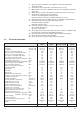
4. GAS ADJUSTMENTS CATEGORY II2H3+ Lower Wobbe Index (15°C;1013mbar) Nominal Delivery Pressure Minimum Delivery Pressure Methane Gas G20 MJ/m3h mbar mbar Liquid Butane Gas G30 45.67 20 17 Liquid Propane Gas G31 80.58 30 20 70.69 37 25 0.72 ---2.02 0.72 ---2.02 23 MFFI Main Burner: n. 13 jets (ø) Consumption (15°C; 1013mbar) Consumption (15°C; 1013mbar) Gas Cock Outlet Pressure max - min mm mc/h Kg/h 1.25 2.72 ---- mbar 11.4- 2.0 mc/h Kg/h 1.25 3.16 ---- mbar 11.4-2.0 mc/h Kg/h 1.30 3.
5. Adjust the soft-light feature; 6. Adjust the delayed lighting feature for the heating system (can be set from 0 to 2 mins.). 5. 26 MAINTENANCE It is recommended that the following checks be made on the boiler at least once a year: 1 - Check the seals for the water connections; replacement of any faulty seals. 2 - Check the gas seals; replacement of any faulty gas seals. 3 - Visual check of the entire unit. 4 - Visual check of the combustion process or analysis of flue gas (see ref 3.
B004 240V MAINS INPUT (3 AMP) 3 8 2 2 T6360B ROOM THERMOSTAT ZONE 2 L 1 N 2 E 3 4 E 8 E 1 2 4 4 E E E 5 N N 3 L 4 N 7 6 L N N L L 3 L 6 L 6 Towerchron MP Link 1-4/6-11 ZONE 2 4 Randall 3020 P and 3060 4 3 E 1 0 1 0 4 1 1 E N 2 6 E E N HW HTG ON ON 1 L N N N 2 2 1 L 2 N L L L L L 1 1 2 ZONE 1 PROGRAMMER 3 Randall 922, 972 Link L-2-5 ACL LS522, LS722 Towerchron 2000 6 Towerchron FP Link 1-5/4-7-9 3 7 Sunvic ET 1451 Link 2-3
1 2 28 C/P Cylinder thermostat Thermal cut-out 1 C/P 1 8 P 6 2 Not used Sangamo 410 Form 1 Link 3-6 4 8 8 1 2 2 4 4 E E E E E E 4 4 N 7 5 N N N N N 3 3 L 6 6 L L L L L 4 Randall 3020 P and 3060 E E HTG ON E E N N N N 2 2 1 1 N N N N • 3 L L L L 1 1 2 2 L L L L PROGRAMMER 2 6 3 Randall 922, 972 Link L-2-5 10 4 6 Towerchron MP Link 1-4/6-11 10 3 6 Towerchron FP Link 1-5/4-7-9 3 ACL LS522, LS722 6 Sunvic DHP 2201 4 HW
NOTES B004
NOTES B004 30
B004
Merloni TermoSanitari SpA - Italy Commercial subsidiary: MTS (GB) LIMITED MTS Building Hughenden Avenue, High Wycombe Bucks HP13 5FT Telephone: (01494) 755600 Fax: (01494) 459775 Technical Service Hotline: (01494) 539579 B004 - Cod.