discover more @ariston.com G.C.N.: 47-116-88 (24 kW) G.C.N.: 47-116-89 (30 kW) G.C.N.: 47-116-90 (38 kW) G.C.N.: 47-116-85 (24 kW) G.C.N.: 47-116-86 (30 kW) G.C.N.: 47-116-87 (38 kW) G.C.N.: 41-116-49 (18 kW) G.C.N.: 41-116-50 (24 kW) G.C.N.
INDEX Overview.............................................................................................3 General Information.........................................................................4 Advice for the Installer....................................................................4 CE Labelling.......................................................................................4 Data Plate Symbols..........................................................................4 Safety Regulations..
OVERVIEW These instructions are suitable for Clas ONE, Clas System ONE and Clas Net ONE boilers : Do not forgot to complete the Benchmark Commissioning Checklist! The Benchmark Scheme Benchmark places responsibilities on both manufacturers and installers.
OVERVIEW ATTENTION!! THE INSTALLATION AND FIRST IGNITION OF THE BOILER MUST BE PERFORMED BY GAS SAFE REGISTERED ENGINEER IN COMPLIANCE WITH GAS SAFETY (INSTILLATION & USE) REGULATIONS AND ALL OTHER NATIONAL REGULATIONS REGARDING INSTALLATION, AND IN CONFORMITY WITH ANY REQUIREMENTS ESTABLISHED BY LOCAL AUTHORITIES AND PUBLIC HEALTH ORGANISATIONS.
OVERVIEW SAFETY REGULATION Key to symbols: Failure to comply with this warning implies the risk of personal injury, in some circumstances even fatal Failure to comply with this warning implies the risk of damage, in some circumstances even serious, to property, plants or animals. Install the appliance on a solid wall which is not subject to vibration. Noisy operation. When drilling holes in the wall for installation purposes, take care not to damage any electrical wiring or existing piping.
OVERVIEW Handle the appliance with suitable protection and with care. Damage to the appliance or surrounding objects from shocks, knocks, incisions and squashing. During all work procedures, wear individual protective clothing and equipment. Personal injury caused by electrocution, falling splinters or fragments, inhalation of dust, shocks, cuts, puncture wounds, abrasions, noise and vibration.
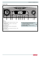
PRODUCT DESCRIPTION CONTROL PANEL 9 1 2 3 4 Legend: 1. Display 2. Domestic Hot Water adjustment button +/- (a) 3. MODE button (Operation mode selection summer/winter) 4. COMFORT button 5. ON/OFF button 6. Auto button (To activate Thermoregulation) 7. RESET button 8 Heating temperature adjustument button +/- (b) 9. Time clock 10.
PRODUCT DESCRIPTION DISPLAY Legend: Digits indicating: - boiler status - temperature indication with bar level - error code signals (ERROR) - Request press RESET button (boiler block) - menu settings Technical assistance request Flame detected with indication of power used Heating operation set Heating operation active Hot water operation set Hot water operation active Hot Water Comfort activated Boiler off with antifreeze function active Anti-frost Function Active AUTO AUTO function activated High effici
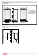
PRODUCT DESCRIPTION Overall view CLAS ONE / CLAS NET ONE 1. 2. 3. 4. 5. 6. 7. 8 9. 10. 12. 13. 14. 15. 16. 17. 18. 19. 20. Flue connector Air relief valve C.H. Flow temperature probe Main heat exchanger Detection Electrode Air/Gas Mixer Secondary heat exchanger Condensate trap C.H. pressure relief valve Gas valve C.H. circuit filter Modulating circulation Pump with air release valve D.H.W. Flow switch Diverter valve Switch On-Off C.H.
PRODUCT DESCRIPTION Overall Dimensions CLAS SYSTEM ONE CLAS ONE / CLAS NET ONE 200 120 200 120 180 25 200 120 200 120 67 67 65 150 315 (Mod. 24) 385 (Mod. 30/35) 28 65 350 Minimum clearances In order to allow easy access to the boiler for maintenance operations, The boiler must be installed in accordance with the clearances stated below. 50 50 300 450 10 / 745 132 67 65 28 745 745 A. Central Heating Flow B. Domestic Hot Water Outlet C. Gas Inlet D. Domestic Cold Water Inlet E.
INSTALLATION Reference Standards In the United Kingdom, the installation and initial start-up of the boiler must be by a Gas Safe registered installer in accordance with the installation standards currently in effect, as well as with any and all local health and safety standards i.e. Gas Safe. In the Republic of Ireland the installation and initial start-up of the appliance must be carried out by a Competent Person in accordance with the current edition of I.S.
INSTALLATION INSTALLATION Gas Supply The gas installation and tightness testing must be in accordance with the requirements of BS6891. Ensure that the pipe size is adequate for demand including other gas appliances on the same supply. The use of a corrosion inhibitor in the sysem is recommended to prevent corrosion (sludge) damaging the boiler and system; Electrical Supply The appliance requires an earthed 230V - 50 Hz supply and must be in accordance with current I.E.E. regulations.
INSTALLATION overflow pipe. The condensate discharge pipe must have a minimum diameter of 22mm, must have a continuous fall and preferably be installed and terminated to prevent freezing. The discharge pipe must be terminated in a suitable position: i) 2. External termination of condensate drainage pipe via internal discharge branch (e.g. sink waste) and condensate siphon. Connecting into an internal soil stack (at least 450mm above the invert of the stack).
INSTALLATION INSTALLATION Installing the Boiler Please check that you are familiar with the installation requirement before commencing work (pages 11 - 15).
INSTALLATION Gas connection Make sure, using the labels on the packaging and the data plate on the appliance itself, that the boiler is in the correct country and that the gas category for which the boiler was designed corresponds to one of the categories available in the country where it will be used. The gas supply piping must be created and measured out in compliance with specific legal requirements and in accordance with the maximum power of the boiler.
INSTALLATION INSTALLATION To calculate the size of the heating installation, refer to the "Available pressure" graph below. Underfloor heating For appliances with underfloor heating, it is possible but not necessary to fit a safety thermostat onto the underfloor heating outlet. For the electrical connection of the thermostat see the section on “Electrical connections - pages 28-29”.
INSTALLATION Water circuit diagram 1 1 3 3 4 4 5 6 21 5 6 21 20 7 20 7 8 19 9 18 19 9 18 17 10 15 14 13 12 11 A 1. 3. 4. 5. 6. 7. 8. 9. 10. 11. 12. 13. 14. 15. 16. 17. 18. 19. 20. 21.
INSTALLATION INSTALLATION Connecting the Flue Flue System The provision for satisfactory flue termination must be made as described in BS 5440-1. The appliance must be installed so that the flue terminal is exposed to outdoor air. The terminal must not discharge into another room or space such as an outhouse or lean-to. It is important that the position of the terminal allows a free passage of air across it at all times.
INSTALLATION Warning The exhaust gas ducts must not be in contact with or close to inflammable material and must not pass through building structures or walls made of inflammable material. When replacing an old appliance, the flue system must be changed. Important Ensure that the flue is not blocked. Ensure that the flue is supported and assembled in accordance with these instructions.
INSTALLATION INSTALLATION Clamp Screws Seal Fig. 4 Fitting the 5” Flue (Ø 80 / 125 Horizontal/vertical) Once the boiler has been positioned on the wall, it is necessary to insert the Ø80/125 adaptor (Fig. 5) for both horizontal and vertical flue runs into the boiler flue socket (not supplied with flue kit - Part No 3318095). Push the adaptor onto the boilers flue connection, grease the seals then add extensions or elbows as required, secure the adaptor, using the clamp and screws provided.
INSTALLATION Fitting the Coaxial Flue (Ø 60 / 100 Vertical) Note: See table for maximum and minimum flue runs. Contents: 1x Conical Adaptor (60/100mm) 1x Vertical Flue Kit (80/125mm) The vertical flue kit is supplied with a specially designed weather proof terminal fitted, it can be used either with a flat roof or a pitched roof.
INSTALLATION INSTALLATION Fitting the Twin Pipe (Ø80 / 80) When siting the twin flue pipe, the air intake and exhaust terminals must terminate on the same wall, the centres of the terminals must be a minimum of 280 mm apart and the air intake must not be sited above the exhaust terminal (refer to Fig. 10). The air intake pipe can be run horizontally, however, the terminal and the final 1 metre of flue must be installed either horizontally or with a slight fall away from the boiler to avoid rain ingress.
INSTALLATION 180 105 195 120 Fig. 9 For coaxial systems, the maximum development value, mentioned in the table below also takes into account an elbow. For twin flue systems the maximum development value, mentioned in the table includes the exhaust gas/air intake terminal. AIR INTAKE MUST NOT BE FITTED ABOVE THE EXHAUST AIR INTAKE EXHAUST Twin flue systems outlets should respect the following instructions: 1- Use the same ø 80 mm flue pipes for the air intakes and exhaust gas ducts.
INSTALLATION INSTALLATION Table of flue gas exhaust duct lengths Maximum Extension Exhaust-air (m) FLUE TYPE Coaxial System CLAS ONE / CLAS NET ONE Diameter of pipe (mm) CLAS ONE SYSTEM 24 30 38 18 24 30 C13 C33 C43 8 7 6 8 8 7 ø 60/100 C13 C33 C43 33 24 27 32 33 24 ø 80/125 S1 = S2 Twin-pipe System C13 24/24 26/26 16/16 36/36 24/24 26/26 C33 48/48 40/40 32/32 48/48 40/40 32/32 C43 24/24 26/26 16/16 36/36 24/24 26/26 C53 S1 + S2 60 50 S1 + S2 35 50 60
INSTALLATION WARNING! BEFORE PERFORMING ANY WORK ON THE BOILER, FIRST DISCONNECT IT FROM THE ELECTRICAL POWER SUPPLY USING THE EXTERNAL BIPOLAR SWITCH AND REMOVE THE FUSE. Peripheral unit connection To access peripheral unit connections carry out the following steps: - Disconnect the boiler from the power supply - Remove the casing - Rotate the control panel while pulling it forwards - Unhook the two clips to have access to the peripherical connections and the main P.C.B.
INSTALLATION INSTALLATION Room Thermostat / Remote Clock Connection To connect a room thermostat, it is necessary to: 1. Open the control panel 2. Loosen the cable clamp using a screwdriver and insert the wires leading from the room thermostat 3. Connect the wires to the terminals as indicated in the figure below, removing the link 4. If a remote time clock is to be fitted, using a volt free switching time clock connect the switching wires from the time clock following points 1 - 3 above 5.
INSTALLATION Fitting instructions for: • Internal mechanical time clock • Internal RF receiver for Ariston programmable room thermostat These instructions to be used in conjunction with the appliance installation instructions. Ensure the appliance is electrically isolated before working on the appliance. Remove the outer casing, and remove the front control panel by removing the 2 securing screws.
INSTALLATION INSTALLATION Electrical diagram For increased safety, ask a qualified technician to perform a thorough check of the electrical system. The manufacturer is not responsible for any damage caused by the lack of a suitable earthing system or by the malfunctioning of the electricity mains supply. CLAS ONE CLAS NET ONE NL 230 V 230 V 230 V 230 V T B TA2 BUS FLOOR SE TNK Detection/Ignition electrode 230 V 230 V SOL TA1 N L Bl C.H. return temperature probe Bl C.H.
INSTALLATION CLAS SYSTEM ONE NL 230 V 230 V 230 V 230 V T B TA2 BUS FLOOR SE TNK Detection/Ignition electrode 230 V 230 V SOL TA1 N L Bl C.H. return temperature probe C.H.
HW CH ON OFF ON OFF L N E REMOTE 2 CHANNEL PROGRAMMER LN 240V 3AMP L N Earths omitted for clarity MOTOR C/H 2 PORT VALVE TERMINAL STRIP R/STAT CYL STAT L N BUS TA2 Boiler SE Remove Link TNK SOL TA1 Note: Boiler switching on TA1 is low voltage, use a seperate cable to supply TA1. Do not use 5 core cable. MOTOR H/W 2 PORT VALVE 30 / INSTALLATION INSTALLATION S plan wiring diagram.
INSTALLATION S plan wiring diagram using an outside sensor. ON OFF ON OFF L N E REMOTE 2 CHANNEL PROGRAMMER LN 240V 3AMP L N TERMINAL STRIP Earths omitted for clarity MOTOR C/H 2 PORT VALVE R/STAT CYL STAT Change parameter: 223 from 0 to 1 521 from 1 to 3 421 from 1 to 0 Activate Auto Function L N Outside sensor Remove Links BUS TA2 SE TNK SOL TA1 Boiler Note: Boiler switching on TA1 & TA2 is low voltage. Use a separate cable to supply TA1 & TA2.
COMMISSIONING Initial preparation Ariston Thermo UK Ltd support the benchmark initiative. On pages 77 and 78 of this manual the Benchmark Commissioning Checklist and Service interval Record can be found. It is important that this is completed in the presence of your customer, they are shown how to use it, and it is signed by them. Please instruct your customer that they must have this manual with them whenever they contact a service engineer or us.
COMMISSIONING FIRST IGNITION OPERATION Date . . . . . . . . . . . . . . . . . . . . . . . . . Installer . . . . . . . . . . . . . . . . . . . . . . 1. Check the electrical supply. 2. Check the type of gas and change the gas if necessary. Complete ................................................................................ Complete ................................................................................ 4. Measure the gas inlet. 5.
COMMISSIONING Ignition procedure Press the ON/OFF button on the control panel to switch on the boiler. The display shows: ● the operating mode: winter First ignition 1. Make sure that: - The gas valve is closed; - The electrical connection has been properly carried out.
COMMISSIONING Combustion checking procedure The order of operations for this procedure must always be respected. Refer to Technical Bulletin 143 on Gas Safe Register website for further information on combustion analysis of domestic boilers. Operation 1 - Supply pressure check Loosen the screw 1 and insert the pressure gauge connection pipe into the pipe tap. Switch the boiler on at maximum power. To activate combustion test function: - Press the mode selector to ensure the icons displayed.
COMMISSIONING Checking slow ignition power The soft light can be adjusted between the maximum power (shown on the display as “100”, i.e. 100%) and the minimum power (shown on the display as “1”, i.e. 1%). To check the slow ignition power, access menu 2/sub menu 2/ parameter 0. 2 1 If the value measured corresponds to the value given in the table, adjustment is complete, otherwise start the setting procedure again.
COMMISSIONING Converting the appliance from Natural gas to LPG AUTO function These appliances are designed to operate with different gas types. The appliance must only be converted for use with a different gas type by a Gas Safe Registered installer. To convert the appliance to LPG: (use these instructions in conjunction with the Instruction sheet supplied with the LPG Kit). 22 1. Electrically isolate the appliance (fig 1) 2. Turn off the gas supply (fig 2) 3.
BOILER PROTECTION DEVICES Boiler protection devices The boiler is protected from malfunctioning by means of internal checks performed by the electronic microprocessor P.C.B., which stops the boiler from operating if necessary. In the event of the boiler being shut off in this manner, a code appears on the display which refers to the type of shut-off and the reason behind it.
BOILER PROTECTION DEVICES Ignition and Detecion 5 01 No flame detected 5 02 Flame detected with gas valve closed 5 04 Flame lift 5 P1 1st Ignition Failed 5 P2 2nd Ignition Failed 5 P3 Flame cut-off Air Inlet / Flue gas outlet 6 10 Overheat (Main heat exchanger) 6 12 Insufficient fan speed Multi-zone Heating (Heating Zone Modules - optional) 7 01 Zone 1 send sensor defective 7 02 Zone 2 send sensor defective 7 03 Zone 3 send sensor defective 7 11 Zone 1 return sensor defective 7 12 Zone 2 re
SETTINGS - ADJUSTMENT - PROBLEM IDENTIFICATION MENUS Accessing the settings - adjustment - problem identification menus The boiler can be used to manage the heating and domestic hot water production system in its entirety. Navigation within the menus enables the boiler system + connected peripheral units to be customised, optimising operation for maximum comfort and maximum saving. It also provides important information relating to the efficient operation of the boiler.
Description value default setting Parameter sub-menu menu SETTINGS - ADJUSTMENT - PROBLEM IDENTIFICATION MENUS SERVICE CODE Press the button “+” to select code 234 and press Ok.
menu sub-menu Parameter default setting SETTINGS - ADJUSTMENT - PROBLEM IDENTIFICATION MENUS 2 2 4 4 BOILER PARAMETER - PART 2 3 Post-ventilation after heating request 2 4 4 2 4 5 Circulation pump MAX speed from 75 to 100 2 2 4 4 6 7 Circulation pump MIN speed Device indicator for heating circuit pressure from 40 to 100 0 = temperature sensor only 1 = pressure switch at minimum 2 = pressure sensor 1 RESERVED FOR TECHNICAL ASSISTANCE Only if the PCB is changed 2 2 4 4 8 9
2 7 2 2 8 8 1 Description value press OK button for 5 seconds Bleed cycle 4 RESET MENU’ 2 0 Automatically resetting to the default setting Reset in menu 2 OK = yes ESC = no ZONE 1 PARAMETER 4 4 0 0 ZONE 1 TEMPERATURE SETTING 2 Heating fixed temperature setting “Heating fixed temp” from 35 to 82 °C (high temperature - para. 420 =1) from 20 to 45 °C (high temperature - para.
menu sub-menu Parameter default setting SETTINGS - ADJUSTMENT - PROBLEM IDENTIFICATION MENUS 4 2 4 5 Compensation from 0 to 20 20 if setting = 0, the temperature taken from the ambient sensor does not affect the calculation of the setting. If setting = 20, the temperature taken has maximum influence on the setting.
sub-menu Parameter 5 5 3 3 DIAGNOSTICS 4 Zone 2 heat request 6 6 6 ZONE 3 PARAMETER 0 ZONE 3 TEMPERATURE SETTING 0 2 Heating fixed temperature setting “Heating fixed temp” 6 6 Description value default setting menu SETTINGS - ADJUSTMENT - PROBLEM IDENTIFICATION MENUS 0 = OFF 1 = ON from 35 to 82 °C (high temperature - para. 420 =1) from 20 to 45 °C (high temperature - para.
menu sub-menu Parameter default setting SETTINGS - ADJUSTMENT - PROBLEM IDENTIFICATION MENUS Description 8 0 3 Boiler Life Time (h x 10) 8 0 4 Time of fan ON (h x 10) 8 0 5 Number of fan cycles (n x10) 8 0 6 Number of flame detection in CH (n x10) 8 1 7 Number of flame detection in DHW (n x10) 8 1 8 1 BOILER STATISTICS-2 0 Number of hours burner operating in heater mode (xxh/10) 8 1 1 Number of hours burner operating in hot water mode (xxh/10) 8 1 2 Number of flame sepa
MAINTENANCE Important Maintenance is an essential part of the safe and efficient operation of the boiler and ensures its durability. It should be performed according to the instructions given in current legislation. Perform combustion analysis regularly in order to check the operating efficiency of the boiler and to make sure any polluting substances released are within the boundaries set by current legislation.
MAINTENANCE GUIDE 1. GENERAL ACCESS Remove the front panel 1.0 Disconnect the boiler Before beginning maintenance work: a. Disconnect the appliance from the electricity supply. Press the ON/OFF button and wait 1 minute (the 3-way valve turn on Stand-by position) ATTENTION!! With the 3-way valve on heating position is not possible to remove the motor. Turn the external bipolar switch to the “OFF” position. b. Close the gas valve and the central heating and domestic hot water system valves.
MAINTENANCE GUIDE 2. ELECTRICAL UNIT 2.2 Fuse 2.
MAINTENANCE GUIDE 2.3 Main P.C.B. 2.4 Display P.C.B. Tools Tools TIME 5 min After opening the control box, disconnect the elctrical plug connections TIME 5 min Unscrews the two screws and pull the assembly towards you 1 1 Disconnect the elctrical plug connections and unhook and remove the P.C.B. Unhook and remove the P.C.B.
MAINTENANCE GUIDE 2.5 Time clock Tools TIME 5 min Unscrews the two screws and pull the assembly towards you 1 Disconnect the elctrical plug connections. Unscrew the four screws and remove the Time clock.
MAINTENANCE GUIDE 3. HYDRAULIC UNIT Rotate clockvise to unhook the locking ring. 3.1 RIGHT HAND HYDRAULIC BLOCK ASSEMBLY 1 9 2 8 3 2 7 6 Remove the 3 way valve motor. 11 10 4 Legend: 1 - Diverter valve motor 2 - Diverter valve 3 - D.H.W. flow switch assembly 4 - C.H. drain valve 6 - Central heating filter 7 - Pump 8 - Primary water pressure switch 9 - Auto air vent 10 - Central Heating return 11 - Cold water inlet (D.H.W.) 3 3.2.
MAINTENANCE GUIDE 3.3 Draining 3.5 Primary water pressure sensor Tools Tools TIME TIME 5 min Turn the drain valve anti-clockwise to open and drain the water from the boiler 1 Drain the boiler (see 3.3). Slide the fixing clip, (it is held captive) unplug the electrical connector and lift the sensor from the assembly. 1 3.4 Automatic air vent 2 Tools TIME 5 min 5 min Drain the boiler (see 3.3). Unscrew anticlockwise the AAV from the assembly.
MAINTENANCE GUIDE 3.6 Pump Remove the sensor (see 3.5) Tools TIME 10 min Drain the boiler (see 3.3). Remove the clip and the two screws 4 1 Remove the AAV (see 3.
MAINTENANCE GUIDE 3.7 C.H. Filter 3.8 D.H.W. Flow switch assembly Tools Tools TIME Drain the boiler (see 3.3). Remove the clip and remove the pressure gauge 5 min TIME 10 min Drain the boiler (see 3.3). Remove the clip and pull the flow switch assembly upward.
MAINTENANCE GUIDE 3.9 LEFT HAND HYDRAULIC BLOCK ASSEMBLY 3 1 2 3 4 Legend: 1 - By-pass assembly 2 - Safety valve 3 - Central heating flow 4 - Domestic hot water outlet 3.10 Secondary heat exchanger 4 Tools TIME 10 min Drain primary and domestic hot water circuits. Remove the silencer.
MAINTENANCE GUIDE 3.11 Condensate trap 3.12 Safety valve Tools Tools TIME 5 min Disconnect the condensate discherge pipe from the bottom of the boiler. Unscrerw the two screws. TIME Drain the boiler (see 3.3). Disconnect the discharge pipe.
MAINTENANCE GUIDE 3.14 By-pass assembly 3.15 Temperature sensors Tools Tools TIME TIME 5 min Drain the boiler (see 3.3). Remove the clip and pull the assembly towards you 5 min NTC1 : Black NTC2: Red NTC1 1 1 NTC2 Unplug the electrical connectors 2 2 Remove the clip and the temperature sensor IMPORTANT ! Do not use conducting paste for the contact sensors because it will alter the resistance value.
MAINTENANCE GUIDE 3.16 Manual Air vent 3.17 Main heat exchanger Tools Tools TIME 5 min TIME Drain boiler (see 3.3) Unscrew and lift the manual air vent from the exchanger Drain boiler (see 3.3) Remove the silencer 1 1 Isolate the gas supply and disconnect the gas pipe.
MAINTENANCE GUIDE Disconnect the cable of the electrode. Disconnect the plastic pipes from the manual air vent.
MAINTENANCE GUIDE Unscrew the four screws to remove the heat exchanger 9 10 11 / 61
MAINTENANCE GUIDE 4.
MAINTENANCE GUIDE 4.1 Electrode (detection and ignition) 4.2 Burner Tools Tools TIME Unplug the electrode on the control box Remove the screws and pull the electrodes towards you. 1 TIME 5 min Remove the silencer 1 Isolate the gas supply. Disconnect the gas pipe.
MAINTENANCE GUIDE Pull the assembly towards you Remove the ceramic fibre. Remove the four screws and pull the burner toward you. Always replace the burner gasket (*). (*) 3 6 Remove the two screws and remove the electrode Verify and replace the other gaskets if they are damaged or showing signs of deterioration 4.3 Fan Tools 4 TIME Remove the silencer (see 4.3 - 1) Isolate the gas supply. Disconnect the gas pipe (see 4.
MAINTENANCE GUIDE 4.4 Gas Valve Remove the three screws to free the fan. Tools TIME 15 min Remove the two screws under the boiler and disconnect the gas pipe on the top of the gas valve 2 1 Remove the gas valve Remove the three nuts.
MAINTENANCE GUIDE 5. ANNUAL MAINTENANCE Plate heat exchanger Maintenance Interval: As necessary How: To measure specification of DHW performance.
MAINTENANCE GUIDE Primary Heat exchanger Maintenance Interval: Annually How : Visual inspection / Clean as necessary Condensate trap Maintenance Interval: Annually or after cleaning primary heat exchanger How : Visual inspection / Clean as necessary / Add water before replacing Pump Maintenance Interval: At the first ignition and annually How: Check that the AAV is open / Visual inspection / Clean as necessary / 67
TECHNICAL DATA GENERAL NOTE Model: 24 C13(X)-C23-C33(X)-C43(X)-C53(X)C63(X)C83(X)-C93(X) B23-B23P-B33 POWER SPECIFICATIONS Max/min nominal calorific flow rate (Hi) Qn kW 22,0 / 3,7 28,0 / 4,3 31,0 / 5,5 Max/min nominal calorific flow rate (Hs) Qn kW 24,4 / 4,1 31,1 / 4,8 34,4 / 6,1 Domestic hot water max/min nominal calorific flow rate (Hi) Qn kW 26,0 / 3,7 30,0 / 4,3 38,0 / 5,5 Domestic hot water max/min nominal calorific flow rate (Hs) Qn kW 28,9 / 4,1 33,3 / 4,8 42,2 / 6,1 Max/m
TECHNICAL DATA GENERAL NOTE Model: 18 0085CR0393 CE Certification (pin) C13(X)-C23-C33(X)-C43(X)-C53(X)C63(X)C83(X)-C93(X) B23-B23P-B33 POWER SPECIFICATIONS Boiler type Max/min nominal calorific flow rate (Hi) Qn kW 18,0 / 3,7 22,0 / 3,7 28,0 / 4,3 Max/min nominal calorific flow rate (Hs) Qn kW 20,0 / 4,1 24,4 / 4,1 31,1 / 4,8 Domestic hot water max/min nominal calorific flow rate (Hi) Qn kW 18,0 / 3,7 26,0 / 3,7 30,0 / 4,3 Domestic hot water max/min nominal calorific flow rate (Hs) Q
TECHNICAL DATA ErP Data - EU 813/2013 Model: CLAS ONE / CLAS NET ONE Condensing boiler yes/no Low-temperature boiler: yes/no B1 boiler yes/no Cogeneration space heater yes/no Combination heater yes/no Contact details ( Name and address of the manufacturer or its authorised representative) 24 30 38 yes yes yes no no no no no no no no no yes yes yes ARISTON THERMO S.p.A. Viale A.
TECHNICAL DATA ErP Data - EU 813/2013 Model: CLAS SYSTEM ONE Condensing boiler yes/no Low-temperature boiler: yes/no B1 boiler yes/no Cogeneration space heater yes/no Combination heater yes/no Contact details ( Name and address of the manufacturer or its authorised representative) 18 24 30 yes yes yes no no no no no no no no no no no no ARISTON THERMO S.p.A. Viale A.
TECHNICAL DATA Package fiche 1 I Instructions for filling the label for packages of space heater (or combination heater), temperature control and solar device. 1. supplier’s name or trademark; 2. supplier’s model identifier; 3. the seasonal space heating energy efficiency class of the space heater, already filled; 4.
TECHNICAL DATA PACKAGES OF COMBINATION HEATER, TEMPERATURE CONTROL AND SOLAR DEVICE The fiche for packages of combination heater, temperature control and solar device shall contain the elements set out in points (a) and (b): a) the elements set out in Figure 1, respectively, for evaluating the seasonal space heating energy efficiency of a package of combination heater, temperature control and solar device, including the following information: - I: the value of the seasonal space heating energy efficiency of
TECHNICAL DATA Figure 1 1 Seasonal space heating energy efficiency of boiler Temperature control From fiche of temperature control ‘I’ Class I = 1%, II = 2%, III = 1,5%, IV = 2%, V = 3%, VI = 4 %, VII = 3,5%, VIII = 5% Supplementary boiler From fiche of boiler + Seasonal space heating energy efficiency (in %) ( 2 3 - ‘I’ ) x 0,1 = % % % Solar contribution - From fiche of solar device Collector size ( in m ) Tank volume ( in m ) 2 ( ‘III’ x 3 + ‘IV’ x Collector efficiency ( in %) ) x 0,9 x
TECHNICAL DATA Figure 5 Water heating energy efficiency of combination heater 1 ‘I’ Declared load profile: Solar contribution - From fiche of solar device % Auxiliary electricity (1,1 x ‘I’ - 10%) x ‘II’ - ‘III’ + - ‘I’ = Water heating energy efficiency of package under average climate 2 % 3 % Water heating energy efficiency class of package under average climate C B A + ++ +++ G F E D M < 27 % ≥ 27 % ≥ 30 % ≥ 33 % ≥ 36 % ≥ 39 % ≥ 65 % ≥ 100 % ≥ 130 % ≥ 163 % L < 27 % ≥ 27 %
GAS BOILER SYSTEM COMMISSIONING CHECKLIST This Commissioning Checklist is to be completed in full by the competent person who commissioned the boiler as a means of demonstrating compliance with the appropriate Building Regulations and then handed to the customer to keep for future reference. Failure to install and commission according to the manufacturer’s instructions and complete this Benchmark Commissioning Checklist will invalidate the warranty. This does not affect the customer’s statutory rights.
SERVICE RECORD It is recommended that your heating system is serviced regularly and that the appropriate Service Interval Record is completed. Service Provider Before completing the appropriate Service Record below, please ensure you have carried out the service as described in the manufacturer’s instructions. Always use the manufacturer’s specified spare part when replacing controls.
ITALIAN DESIGN Ariston Thermo UK Ltd ariston.co.