,QVWDOODWLRQ DQG 6HUYLFLQJ LQVWUXFWLRQV E-Combi 24/30/38 E-System 24/30 CONDENSING WALL HUNG COMBINATION BOILER G.C.N : 47 - 116 - 62 (24 kW) G.C.N : 47 - 116 - 63 (30 kW) G.C.N : 47 - 116 - 64 (38 kW) CONDENSING WALL HUNG O.H. BOILER G.C.N : 41 - 116 - 34 (24 kW) G.C.
INDEX Overview ..........................................................................................3 General Information ............................................................................................. 3 Advice for the Installer......................................................................................... 4 CE Labelling ............................................................................................................. 4 Data Plate Symbols .............................
overview These instructions are suitable for E-COMBI and E-SYSTEM boilers : Do not forget to complete the Benchmark Commisioning Checklist. The Benchmark Scheme Benchmark places responsibilities on both manufacturers and installers.
overview Advice for the installer Symbols used on the data plate The installation and first ignition of the boiler must be performed by qualified personnel in compliance with current national regulations regarding installation, and in conformity with any requirements established by local authorities and public health organisations.
overview Safety regulations Key to symbols: Failure to comply with this warning implies the risk of personal injury, in some circumstances even fatal. Failure to comply with this warning implies the risk of damage, in some circumstances even serious, to property, plants or animals. Install the appliance on a solid wall which is not subject to vibration. Noisiness during operation. When drilling holes in the wall for installation purposes, take care not to damage any electrical wiring or existing piping.
product description Control panel E-COMBI 1 40° 2 50° 60° 70° 80° 10 90° 9 3 8 on/off I O 4 7 6 5 E-SYSTEM 1 40° 2 50° 60° 70° 80° 90° 10 9 3 on/off 4 5 Legend : 1. 2. 3. 4. 5. 6. 7. 8.
product description Overall view E-COMBI 1 E-SYSTEM 1 22 2 22 2 21 21 3 3 20 20 4 19 4 18 18 5 6 19 5 6 17 17 7 7 16 16 15 8 14 14 9 9 10 13 10 12 12 11 11 1. 2. 3. 4. 5. 6. 7. 8. 9. 10. 11. 12. Flue connector Manual air vent Burner Detection electrode C.H. Return temperature probe C.H. Flow temperature probe Gas valve Secondary heat exchanger Trap C.H. pressure relief valve Electrical box C.H. circuit filter 13. 14. 15. 16. 17. 18. 19. 20. 21. 22. D.H.W.
product description Minimum clearances Overall Dimensions In order to allow easy access to the boiler for maintenance operations, the boiler must be installed in accordance with the clearances stated to the left (opposite). E-COMBI 200 120 180 5 5 450 65 67 67 65 28 300 770 770 300 120 25 200 150 315 mod. 24 385 mod. 30/35 E-SYSTEM 200 120 180 132 150 315 mod. 24 385 mod. 30 132 A. Central Heating Flow B. Domestic Hot Water Outlet C. Gas Inlet D. Domestic Cold Water Inlet E.
product description POWER SPECIFICATIONS GENERAL NOTE Technical Data Model E-COMBI 24 CE Certification (pin) Boiler type B23-B33-C13-C33-C43-C53-C83 Max/min nominal calorific flow rate (Pci) Qn kW 22.0/5.5 28.0/6.5 31.0/7.5 Max/min nominal calorific flow rate (Pcs) Qn kW 24.4/6.1 31.1/7.2 34.4/8.3 Domestic hot water max/min nominal calorific flow rate (Pci) Qn kW 25.0/5.5 30.0/6.5 38.0/7.5 Domestic hot water max/min nominal calorific flow rate (Pcs) Qn kW 27.8/6.1 33.3/7.2 42.
POWER SPECIFICATIONS GENERAL NOTE product description Model E-SYSTEM 24 CE Certification (pin) 0085BR0347 Boiler type B23-B33-C13-C33-C43-C53-C83 Max/min nominal calorific flow rate (Pci) Qn kW 22.0/5.5 28.0/6.5 Max/min nominal calorific flow rate (Pcs) Qn kW 24.4/6.1 31.1/7.2 Max/min power output (80°C-60°C) Pn kW 21.6/5.2 27.4/6.2 Max/min power output (50°C-30°C) Pn kW 23.5/5.8 29.5/6.9 Combustion efficiency (of flue gas) % 97.9 97.
installation Reference Standards In the United Kingdom, the installation and initial start-up of the boiler must be by a Gas Safe registered installer in accordance with the installation standards currently in effect, as well as with any and all local health and safety standards i.e. Gas Safe. In the Republic of Ireland the installation and initial start-up of the appliance must be carried out by a Competent Person in accordance with the current edition of I.S.
installation Flushing and Water Treatment Location The boiler is equipped with a stainless steel heat exchanger. The detailed recommendations for water treatment are given in BS 7593:1992 (Treatment of water in domestic hot water central heating systems); the following notes are given for general guidance. If the boiler is installed on an existing system, any unsuitable additives must be removed.
installation Condensate Discharge The condensate discharge hose from the boiler must have a continuous fall of 2.5o and must be inserted by at least 50mm into a suitable acid resistant pipe - e.g. plastic waste or overflow pipe. The condensate discharge pipe must have a minimum diameter of 22mm, must have a continuous fall and preferably be installed and terminated to prevent freezing.
installation Installing the Boiler Please check that you are familiar with the installation requirement before commencing work (pages 7 - 13).
installation Safety Valve Discharge and Condense Outlet Gas connection The pressure relief valve pipe is made of copper. It should terminate below the boiler safely outside the premises. Care should be taken that it does not terminate over an entrance or window or where a discharge of heated water could endanger occupants or passers by.
installation Instructions for opening the casing and performing an internal inspection To calculate the size of the heating installation, refer to the "Available pressure" graph below. Before performing any work on the boiler, first disconnect it from the electrical power supply using the external bipolar switch; removing the fuse and shutting off the gas cock. To access the inside of the boiler, the following is necessary: 1. Remove the casing by unhooking it from the control panel (a) 2.
installation Water circuit diagram E-SYSTEM E-COMBI 1 1 19 2 19 2 18 3 4 17 5 18 3 4 17 5 16 16 6 15 15 7 14 13 8 9 12 11 10 $ 1. 2. 3. 4. 5. 6. 7. 8. 9. 10. 11. 12. 13. 14. 15. 16. 17. 18. 19. % & ' ( 7 14 8 9 10 11 $ & ( Manual air vent Burner Detection electrode C.H. flow temperature probe C.H. return temperature probe Secondary heat exchanger C.H. pressure relief valve By-pass Drain valve Condensate trap C.H. circuit filter D.H.W.
installation Connecting the Flue Flue System The provision for satisfactory flue termination must be made as described in BS 5440-1. The appliance must be installed so that the flue terminal is exposed to outdoor air. The terminal must not discharge into another room or space such as an outhouse or lean-to. It is important that the position of the terminal allows a free passage of air across it at all times.
installation (Ø 60 / 100 Horizontal) Contents: 1x Silicone O-Ring (60mm) 1x Elbow (90°) 2x Wall Seals (Internal & External) 1x Flue Pipe including Terminal (1 metre - 60/100) 2x Flue Clamps 4x Screws 2x Seals Fig. 3 118 Fitting the Coaxial Flue Installation without extension Level Once the boiler has been positioned on the wall, fit the rubber flue seal into the internal flue turret (see diagram opposite), insert the elbow into the socket and rotate to the required position.
installation Fitting the 5” Flue (Ø 80 / 125 Horizontal/vertical) Once the boiler has been positioned on the wall, it is necessary to insert the Ø80/125 adaptor (Fig. 5) for both horizontal and vertical flue runs into the boiler flue socket (not supplied with flue kit - Part No 3318095). Push the adaptor onto the boiler’s flue connection, grease the seals then add extensions or elbows as required, secure the adaptor, using the clamp and screws provided.
installation Before proceeding to fit the flue, ensure that the maximum flue length has not been exceeded (see the tables) and that all elbows and bends have been taken into consideration. For each additional 90° elbow 1 metre must be subtracted from the maximum flue length, and for each 45° 0.5 metres must be subtracted from the maximum flue length (the height of the vertical adaptor and a 45° bend can be seen in Fig. 8). Fitting the Twin Pipe (Ø80 / 80) Fig. 8a Fig.
installation The maximum permissible flue length for twin flue is dependent on the type of run used (see table below). Fig. 9 180 120 105 195 For further information relating to flue runs not illustrated, please contact the Technical Department on 0870 241 8180. For coaxial systems, the maximum flue lengths listed in the table below take into account an elbow. For twin flue systems the maximum flue lengths listed in the table below includes the exhaust gas/air intake terminal.
installation Table of flue gas exhaust duct lengths Maximum Extension Exhaust-air (m) Type Coaxial System E-COMBI 24 E-SYSTEM 24 E-COMBI 30 E-SYSTEM 30 E-COMBI 38 Diameter of pipe (mm) MIN MAX MIN MAX MIN MAX C13 C33 0,5 12 0,5 12 0,5 6 ø 60/100 C13 C33 0,5 36 0,5 36 0,5 18 ø 80/125 C13 C33 Twin-pipe System C53 S1 = S2 0,5/0,5 36/36 S1 = S2 0,5/0,5 1 + S2 1/0,5 48/48 S1 = S2 0,5/0,5 1 + S2 1/83 1/0,5 18/18 1 + S2 1/70 1/0,5 1/42 ø 80/80 ø 80/80 S1 = Air intake S2
installation WARNING Before performing any work on the boiler, first disconnect it from the electrical power supply using the external bipolar switch and remove the fuse. Electrical connections For increased safety, ask a qualified technician to perform a thorough check of the electrical system. The manufacturer is not responsible for any damage caused by the lack of a suitable earthing system or by the malfunctioning of the electricity mains supply.
installation Room Thermostat / Remote Clock Connection The boiler connections for external controls are 12V DC and so only controls of 12V DC that have voltage free contacts should be used. The boiler connections for external controls are 12V DC and so only controls of 12V DC that have voltage free contacts should be used. To connect a room thermostat, it is necessary to: 1. Open the control panel 2. Loosen the cable clamp using a screwdriver and insert the wires leading from the room thermostat 3.
Bk Bk Rd Rd 1 1 CN16 8 7 6 5 4 3 2 1 Bk 1 Bk 1 Br Low water pressure switch Bk 1110 9 8 7 6 5 4 3 2 1 CN12 1110 9 8 7 6 5 4 3 2 1 1 4 Bk Bk CN11 1312 1110 9 8 7 6 5 4 3 2 1 D.H.W. Flow Switch (only E-COMBI) Bk 2 Bk 2 ZONE1 FILLING1 PUMP PUMP SPEED 4 Bk 3 Br 2 Bl 1 TA2 6 TA1 1 5 CN24 4 CN12 Bl Bl FUSE 2AT Gas valve Fan Bl Rd Wh Bk Br Br Br Bl C.H. Return temperature probe Rd Rd Thermal fuse Bl FLAME Detection electrode C.H.
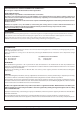
commissioning S Plan Wiring Diagram *Terminals shown are for the ARISTON Unvented Hot Water Cylinder Thermostats Note: Y plan system not suitable.
commissioning Initial preparation Filling of the DHW System (Combi only): At the time of commissioning, complete all relevant sections of the Benchmark Checklist located on the inside back pages of this document. ARISTON Thermo UK LTD Limited support the Benchmark initiative. On pages pages 53 and 54 of this manual the Benchmark Commissioning Checklist and Service interval Record can be found.
commissioning First ignition operation Date . . . . . . . . . . . . Installer . . . . . . . . . . 1. Check the electrical supply. 2. Check the type of gas and change the gas if necessary. 3. Check the gas tightness. Complete . . . . . . Complete . . . . . . Complete . . . . . . 6. Measure the gas inlet pressure. standing + warming pressure 5. Check the exhaust flue. See page 18 6. Fill the installation. See page 30 Complete . . . . . . Complete . . . . . . Complete . . . . . . 7.
commissioning irst ignition 1. Make sure that: 50° 60° 70° 80° 40° - The gas valve is closed; - The electrical connection has been properly carried out. Make sure that the green/yellow earthing wire is connected to an efficient earthing system; - Use a screwdriver to lift the cap on the automatic air relief valve; - Switch on the boiler (by pressing the ON/OFF button), the green led 3 will illuminate indicating that the boiler is ready to operate. Turn the CH button 5 between min. and max position.
commissioning Test function and combustion analysis The boiler has two pressure taps to measure the combustion gas temperature, the combustive air and the concentrations of O2 and CO2 on the outside of the flue gas header. To access these pressure taps, unscrew the screw which holds the blanking cover and its seal together. 50 Only a 2.5 key must be used Minimum gas flow combustion analysis Checking the gas setting To carry out analyses of combustion, the test function must be activated.
boiler protection devices Boiler protection devices The boiler is protected from malfunctioning by means of internal checks performed by the electronic microprocessor P.C.B., which stops the boiler from operating if necessary. In the event of the boiler being shut off in this manner, the led code shows the type of shut-off and the reason behind it.
maintenance Important Maintenance is an essential part of the safe and efficient operation of the boiler and ensures its durability. It should be performed according to the instructions given in current legislation. Perform combustion analysis regularly in order to check the operating efficiency of the boiler and to make sure the combustion is within the boundaries set by current legislation.
maintenance guide General access Tools Time 3 min 1 Unclip the cover to remove Remove the two screws Remove the front panel 2 Lower the electrical box 34 Remove the combustion chamber front panel by releasing the clips
maintenance guide Electrical unit Control box access Tools Time 4 min Time 5 min 1 Remove the front panel as above and pivot the electrical box Remove the two screws and unlock the four clamps to gain access to the control box Fuse Tools 1 Open the control box as above Remove the fuse 35
maintenance guide Main P.C.B. Tools Time 7 min 1 After opening the control boz, disconnect the electrical plug connectors Unscrew the two screwa and remove the PCB Display P.C.B.
maintenance guide Hydraulic Unit Right hand hydraulic block assembly Legend: 1 1. Diverter valve motor 3 2. Diverter valve 4 2 3. Auto air vent 4. Primary water pressure switch 5. Pump 5 6. Central heating filter 7. Non return valve 8. Non return valve assembly 6 9. DHW flow switch assembly 7 10 10. Drain valve 8 11. Central heating return 9 14 13 12 11 12. Domestic cold water intlet 13. Domestic hot water outlet 14.
maintenance guide 3 Way valve unit Tools Time 5 min 1 Unplug the diverter valve cable Remove the clip and lift the motor from the diverter valve body Drain the boiler (see 3.3). Remove the clip and lift the diverter valve from the assembly aligned correctly 2 Draining Tools 1 38 Time 5 min Turn the drain valve anti-clockwise to open and drain the water from the boiler.
maintenance guide Automatic air vent Tools Time 5 min 1 Drain boiler (see 3.3). Remove the clip and lift the AAV from the assembly Primary water pressure sensor Tools Time 5 min 1 Drain boiler (see 3.3).
maintenance guide Pump Tools Time 10 min 1 Drain boiler (see 3.3). Remove the clip and the two screws Disconnect the pipe and then move the pump to the right disengage Remove the pump Remove the sensor (see 3.5) 2 3 Remove the AAV (see 3.
maintenance guide C.H. Filter Tools Time 5 min 1 After opening the control boz, disconnect the electrical plug connectors Unscrew the two screwa and remove the PCB D.H.W. Flow Switch assembly (E-COMBI) Tools Time 5 min 1 Drain boiler (see 3.3).
maintenance guide Left hand Hydraulic block assembly Legend 1. Left hand hydraulic block 2. By-pass assembly 3. Safety valve 4. Central heating flow 1 5. Domestic hot water outlet 2 3 4 5 Secondary Heat Exchanger (E-COMBI) Tools 1 Drain primary and domestic hot water circuits.
maintenance guide Condensate Trap Tools Time 1 5 min Unscrew the condense trap from the condense body Safety valve Tools Time 5 min 1 Drain boiler (see 3.3).
maintenance guide By-Pass Assembly Tools Time 5 min 1 Drain boiler (see 3.3).
maintenance guide Manual Air vent Tools Time 5 min 1 Remove the clip and lift the manual air vent from the exchanger Main Heat Exchanger Tools Time 20 min 1 Drain boiler (see 3.3). Remove the four clips Isolate the gas supply.
maintenance Burner unit Legend 1. Burner 2. Fan 3. Silencer 4. Gas inlet 5. Air inlet 6. Gas valve 7. Mixing tube 8. Detection electrode 9. Ignition electrode 10.
maintenance guide Spark generator Tools Time 5 min Time 5 min 1 Unplug the ignition electrode from the spark generator Remove the screw and the spark generator Electrodes Tools 1 Unplug the electrodes Remove the screws and pull the electrodes towards you.
maintenance guide Burner Tools Time 15 min 1 Remove the silencer Isolate the gas supply. Remove the four Pull the assembly towards you screws and disconnect the gas pipe from the gas valve Note: Any work carried out on the combustion assembly requires a combustion analysis check on completion of work 2 Remove the three screws to free the burner Pull the burner toward you door 2 1 3 Power Length Venturi 24 KW 104.6 mm Ø 42 mm 2. Ignition electrode 30 KW 135.8 mm / 3.
maintenance guide Fan Tools Time 15 min 1 Remove the combustion assembly (see 4.3) Legend: 1. Venturi 2. Gasket 3. Fan Remove the three screws to free the fan.
maintenance guide Gas valve Tools Time 15 min 1 Remove the combustion assembly (see 4.3) Twist the gas valve anti-clockwise to disconnect it from the fan Replacement gas valves are not factory set and will need to be set up (see page 33) Legend Bayonet B ayonet connection c onnecti on 1. Venturi 2. Gas valve 3. Solenoids 4. Inlet test nipple 5. Offset adjustment 6.Throttle adjustment Note: When changing the gas valve, the new gas valve is not preset.
maintenance guide Annual Maintenance Plate heat exchanger Primary Heat exchanger Maintenance Interval: As necessary How: To measure specification of DHW performance.
maintenance guide Fault finding Overheat Insufficient Flame detected Water pressure Ignition electrode/wiring connectors with gas valve closed circulation Bleed heat exchanger Ignition electrode wiring connection onto Pump operation main pcb CH return filter for blockages Circulation around boiler (blockages) Flame lift Insufficient working gas pressure Check flue system for correct assembly/ ntc temperature sensors termination Insufficient water CO2 settings Water pressure gauge for correct
maintenance guide GAS BOILER SYSTEM COMMISSIONING CHECKLIST This Commissioning Checklist is to be completed in full by the competent person who commissioned the boiler as a means of demonstrating compliance with the appropriate Building Regulations and then handed to the customer to keep for future reference. Failure to install and commission this equipment to the manufacturer’s instructions may invalidate the warranty but does not affect statutory rights.
SERVICE RECORD It is recommended that your heating system is serviced regularly and that the appropriate Service Record is completed. Service Provider Before completing the appropriate Service Record below, please ensure you have carried out the service as described in the manufacturer’s instructions. Always use the manufacturer’s specified spare part when replacing controls.
SHORT LIST 407 537 530 538 401 543 136 135 589 517 112 590 134 111 625 607 615 502 616 110 506 ( 6<67(0 ( &2 0 %, ( &20%, 'HVFULSWLRQ 0DQI 3W 1 %851(5 $66(0%/< *$6 6(&7,21 +<'5$8/,& %/2&. (/(&75,&$/ %2; ,*1,7,21 (/(&752'( ,21,=$7,21 (/(&752'( *$6.(7 ' (/(&752'( *$6.(7 &20%867,21 &+$0%(5 /,1,1* .,7 '225 *$6.
Hughenden Avenue High Wycombe Bucks HP13 5FT Telephone: (01494) 755600 Fax: (01494) 459775 Internet: www.ariston.co.uk Technical Advice: 0870 241 8180 Customer Service: 0870 600 9888 Professional Team Limited Suites 9 & 10, Plaza 256 Blanchardstown Corporate Park 2 Ballycoolin Dublin 15 Telephone: (01) 810 3723 Fax: (01) 810 3727 Internet: www.aristonthermo.